Devices And Methods For LED Life Test

a life test and led technology, applied in the field of life test equipment for semiconductor elements, can solve the problems of relative longer lifetime, inability to achieve lifetime tests for a short period, and inability to control the temperature of led

Active Publication Date: 2010-12-30
IND TECH RES INST
View PDF3 Cites 60 Cited by
  • Summary
  • Abstract
  • Description
  • Claims
  • Application Information

AI Technical Summary

Problems solved by technology

LEDs are semiconductor light sources with relatively longer lifetimes. Thus, lifetime tests cannot be accomplished for a short period with normal rating operation conditions.
However, while the temperature of the oven 11 can be controlled, both the current provided from the power supply 13 and the heat-dissipation ability of the holder 12 affect the junction temperature of the LED during the decay test, so that the temperature of the LED can not be controlled.

Method used


Image

  • Devices And Methods For LED Life Test
  • Devices And Methods For LED Life Test
  • Devices And Methods For LED Life Test

Examples


first embodiment

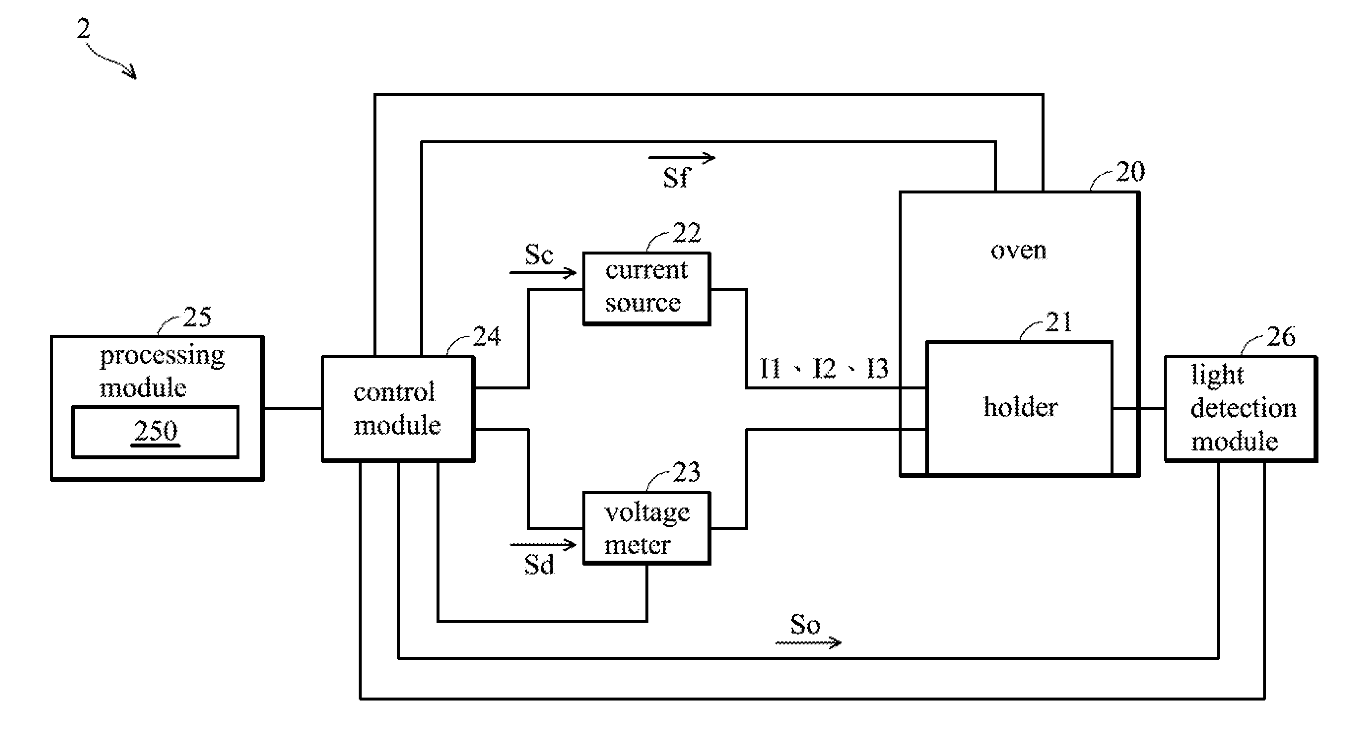
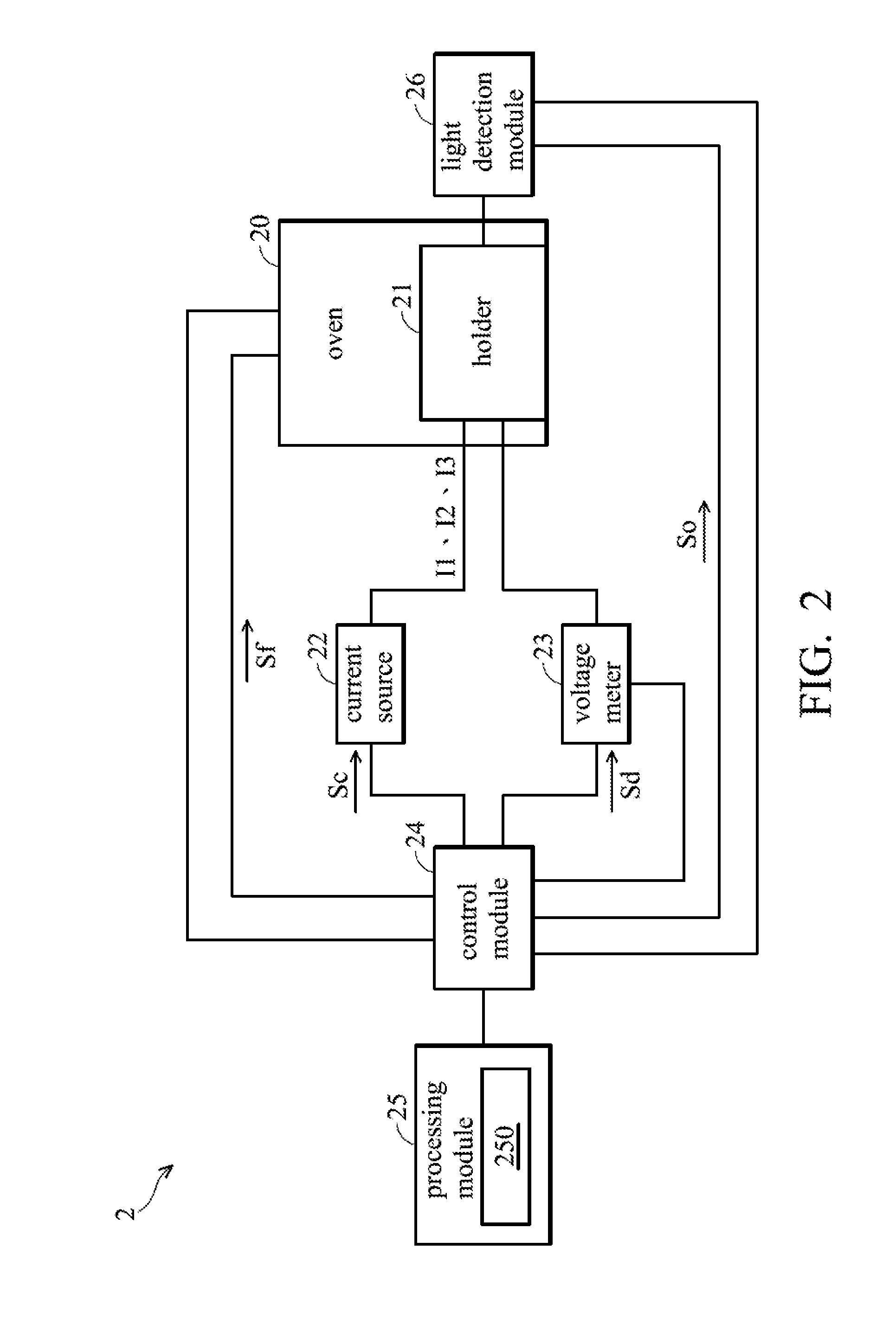
[0023]FIG. 2 shows the first embodiment of a lifetime test equipment. Referring to FIG. 2, a lifetime test equipment 2 is used to test lifetime of an LED and comprises an oven 20, an LED holder 21 disposed in the oven 20, a current source 22, a voltage meter 23, a control module 24, a processing module 25, and a light detection module 26. The LED is disposed on the holder 21. The control module 24 provides a current control signal Sc to the current source 22. The control module 24 also provides a voltage measurement signal Sd for controlling the voltage meter 23 to measure a forward voltage generated by the LED and transmit the measured forward voltage to the processing modules 25. The control module 24 provides a light detection signal So for controlling the light detection module 26 to detect light output of the LED and transmit the detected light output to the processing module 25. The control module 24 further provides an oven-temperature detection signal Sf for detecting a temp...

second embodiment

[0037]According to the second embodiment, the junction temperature of the LED can be obtained by another variation relationship equation between the forward voltages and the oven temperature points. During the period P1, when the processing module 25 obtains the forward voltages V1 and V2 and the oven temperature points T1 and T2, a variation relationship equation between forward voltages V1 and V2 and the oven temperature points T1 and T2 is obtained:

V=A*T+B   (3)

[0038]wherein V represents a forward voltage, T represents an oven temperature point, A represents the slope of the variation relationship equation (3), and B represents the intercept of the variation relationship equation (3). According to Equation (2) and Equation (3), the slope A of the variation relationship equation (3) is the temperature coefficient K.

[0039]During the period P2, the current source 22 is switched to provide the current I2 to the LED for a decay test according to the current control signal Sc. After ev...

third embodiment

[0042]FIG. 5 shows the third exemplary embodiment of a lifetime test equipment. The elements with the same references as in FIGS. 2 and 5 perform the same operations. The lifetime test equipment 5 of FIG. 5 is similar to the lifetime test equipment 2 of FIG. 2, and the difference there between is that the lifetime test equipment 5 is used to test lifetime of a plurality of LEDs. Moreover, the currents I1 and I3 and the current I2 are provided by different current sources. Referring to FIG. 5, the lifetime test equipment 5 comprises an oven 20, an LED holder 21 disposed in the oven 20, current sources 51 and 52, a power switch unit 53, a voltage meter 23, a control module 24, a processing module 25, and a light detection module 26. The LEDs are disposed on the LED holder 21. The control module 24 provides a current control signal Sc1 to the current source 51 and a current control signal Sc2 to the current source 52. The control module 24 provides a voltage measurement signal Sd for c...


PUM


Abstract

A life test device comprises an oven, a current source, a voltage meter, a control module, and a process module. A light-emitting diode (LED) is disposed in the oven. The temperature of the oven is gradually changed in a first period and remains at a set temperature in a second period. The current source provides a first current and a second current to the LED. The voltage meter measures forward voltages of the LED. The control module controls the current source to output the first or second current to the LED and controls the voltage meter to measure the forward voltages of the LED. The process module calculates a junction temperature of the LED according to the forward voltages and a variation relationship formula between the forward voltages and the temperature of the oven.

Description

FIELD OF THE INVENTION[0001]The invention relates to a lifetime test equipment for semiconductor elements, and more particularly to a lifetime test equipment which estimates lifetime of light-emitting diodes (LEDs) by measuring junction temperatures of the LEDs.DESCRIPTION OF THE RELATED ART[0002]Driven by technological development, operation power and light-emitting efficiency of light-emitting diodes (LEDs) have been enhanced. LED applications have been developed from being used as small display backlight sources to main light sources for illumination. Solid-state lighting is the next generation of lighting sources, replacing incandescent lamps and fluorescence lamps. As demand for luminous flux and light-emitting efficiency of LEDs increase, the lifetime of LEDs become more important. Most LEDs suppliers provide estimated lifetime values of LEDs. However, different suppliers may provide different estimated lifetime values for the same type of LEDs. Moreover, different test organi...

Claims


Application Information

Patent Timeline
Patent Type & Authority Applications(United States)
IPC IPC(8): G01R31/26
CPCG01R31/2642G01R31/2635
Inventor CHEN, CHIU-LINGHUANG, SHENG-PANHWANG, FEI-CHANG
Owner IND TECH RES INST
Why Eureka
Try Eureka