
Method and Apparatus for Enabling Multicast Route Leaking Between VRFs in Different VPNs

a multicast route and vpn technology, applied in the field of communication networks, can solve the problem that the receivers in separate vpns cannot be part of the same multicast distribution tree branch, and achieve the effect of efficient ip multicast distribution tr

Inactive Publication Date: 2010-12-30
AVAYA INC
View PDF13 Cites 39 Cited by
  • Summary
  • Abstract
  • Description
  • Claims
  • Application Information

AI Technical Summary

Benefits of technology

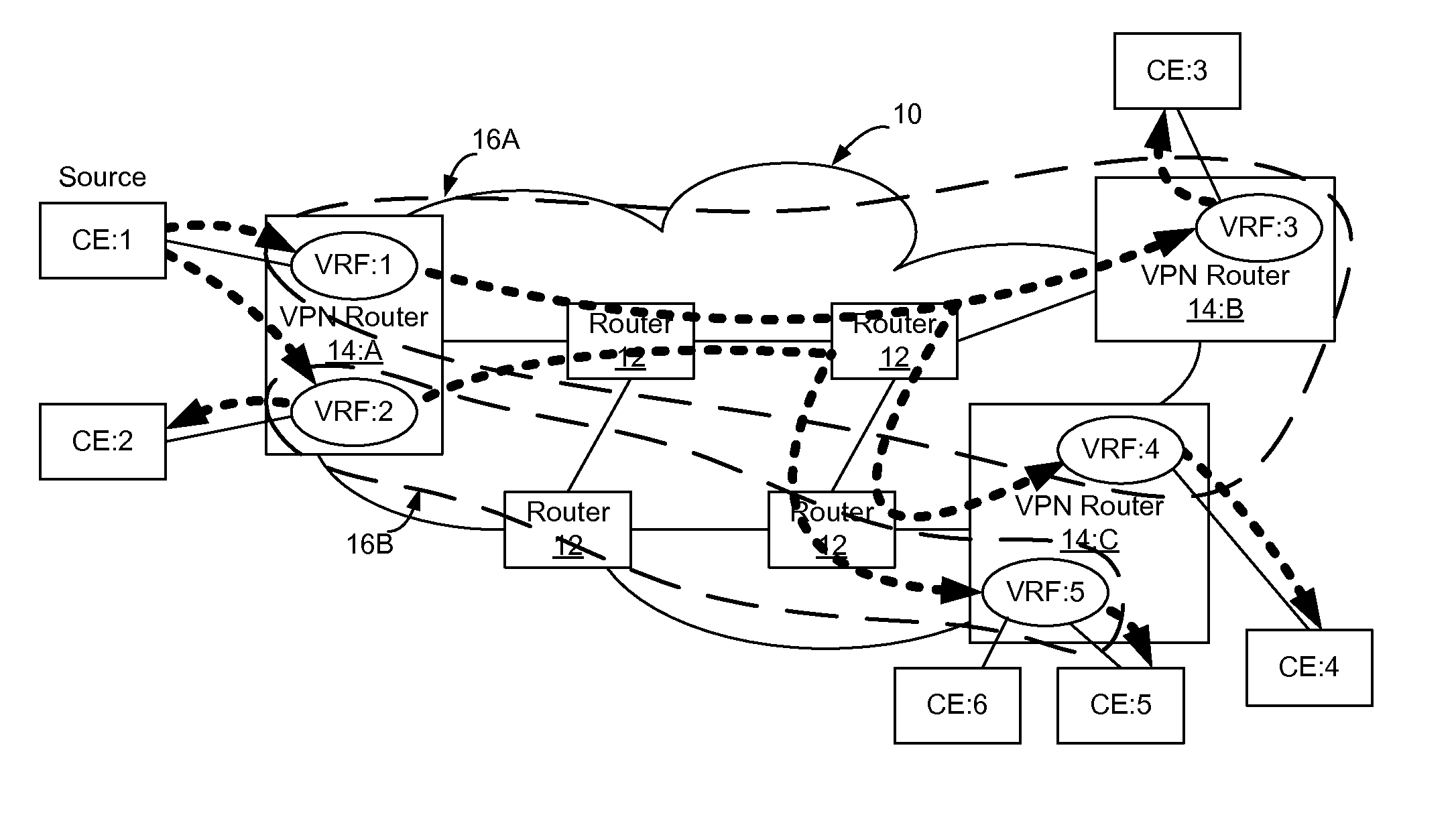
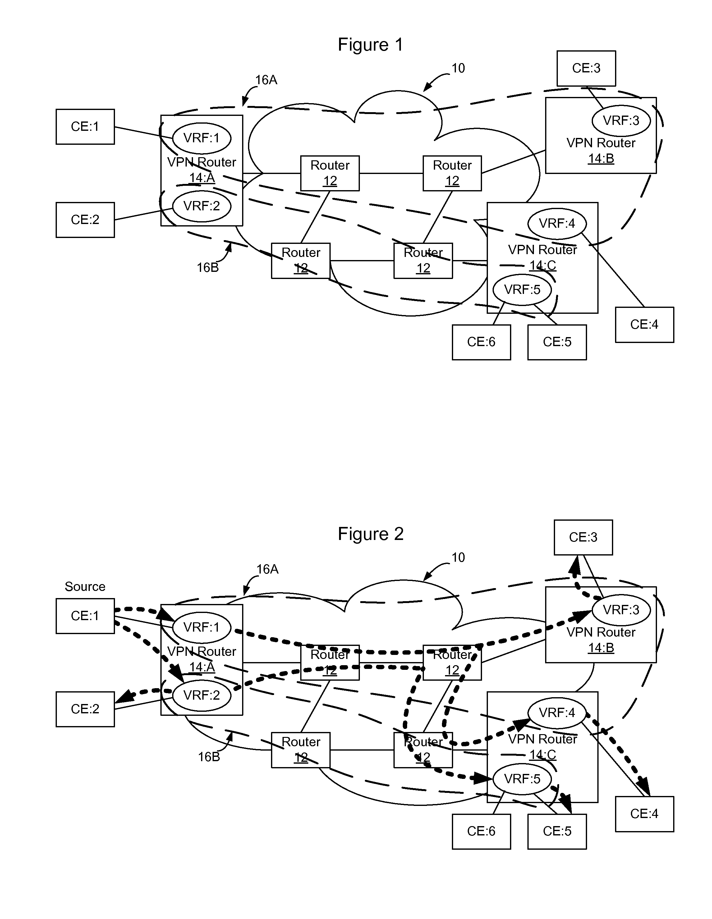
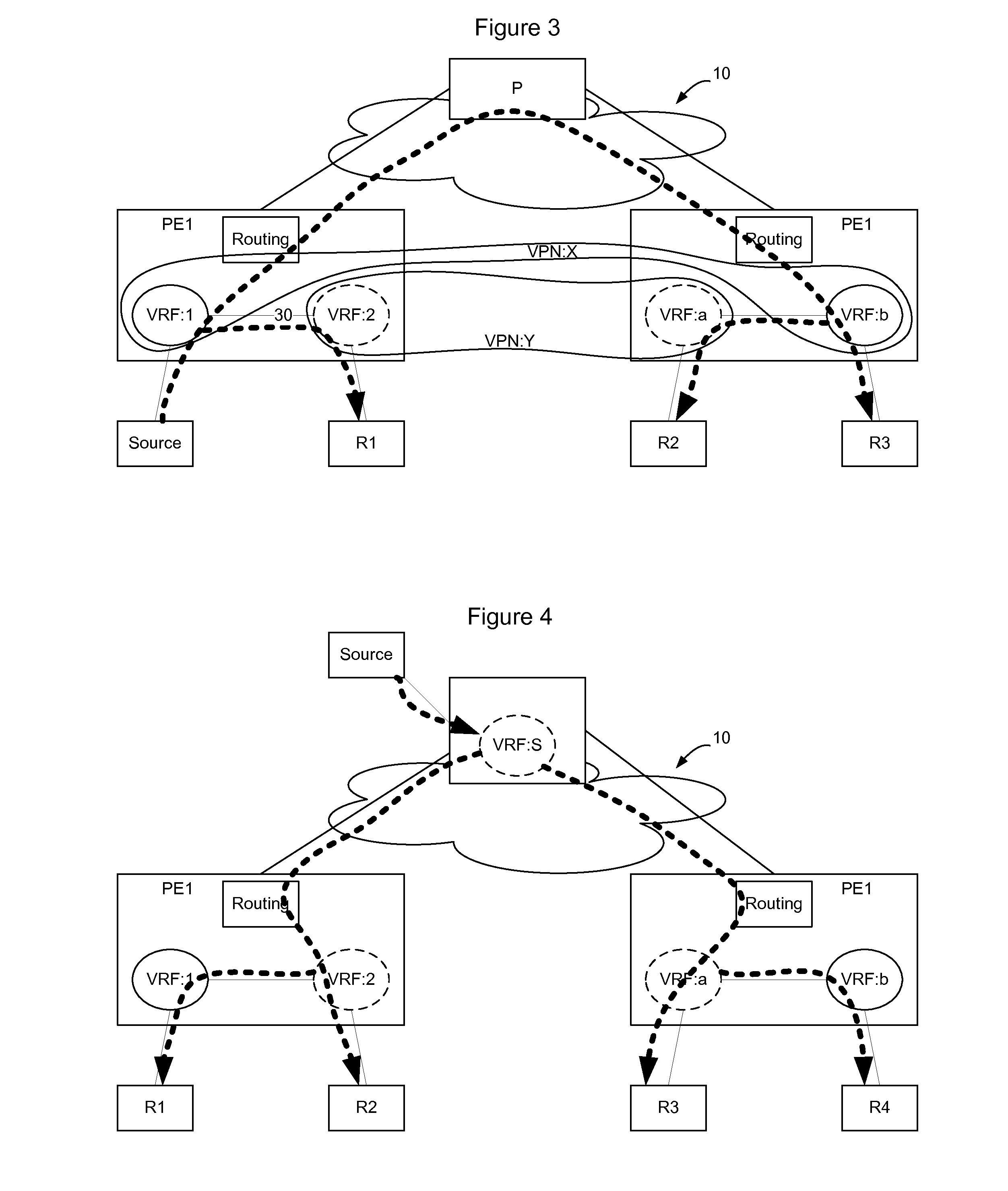
[0013]A method and apparatus for enabling multicast route leaking between VRFs in different VPNs enables receivers in different VPNs to subscribe to the IP multicast and enables an efficient IP multicast distribution tree to be built including subscribers in different VPNs. According to an embodiment, a multicast tree may be built for an IP multicast within a primary VPN to be used to transmit multicast packets within the VPN. The primary VPN may be a VPN including the IP multicast source or may be another VPN. Where VRFs from other VPNs are co-located on PE nodes that have membership in the IP multicast on the primary VPN, rather than implement a separate branch of the tree within their own VPN, the VRFs may implement multicast route leaking to enable local distribution within the PE node from the primary VPN to all other VPNs with attached receivers on the node. This enables a more efficient multicast tree to be built in which local distribution of IP multicast information may occur between VPNs within the PE nodes on the network.

Problems solved by technology

Thus, separate multicast distribution trees may need to be built for each VPN in use on the network, which may cause multiple copies of the multicast content to need to be delivered on the network.
Unfortunately, since VRFs in different VPNs do not share routing information with each other, receivers in the separate VPNS will not be allowed to be part of the same multicast distribution tree branch.

Method used


Image

  • Method and Apparatus for Enabling Multicast Route Leaking Between VRFs in Different VPNs
  • Method and Apparatus for Enabling Multicast Route Leaking Between VRFs in Different VPNs
  • Method and Apparatus for Enabling Multicast Route Leaking Between VRFs in Different VPNs

Examples


Embodiment Construction

[0020]Enterprise consolidation and security considerations are drivers that demand that networks be virtualized. Virtualization of a network enables a virtual network to be created over the physical network so that traffic may be maintained private to the subset of users and nodes that form part of the virtual network. Layer 2 (i.e. Ethernet Virtual Local Area Network VLAN) and Layer 3 (Internet Protocol) based VPNs are functionalities that support network virtualization. There are many types of VPNs, such as MPLS based VPNs (established using IETF RFC 4364 / 2547), Virtual Private LAN Service (VPLS), Pseudowire, and IP-Security (IP-SEC) based VPNs. Other types of VPNs exist as well and this list is not intended to be exhaustive. Use of VPNs enables traffic to be segregated, so that particular traffic may be provided only to selected receivers that are associated with a particular VPN.

[0021]FIG. 1 shows an example communication network 10. In the communication network 10, routers 12 i...


PUM


Abstract

Multicast route leaking between VRFs in different VPNs enables receivers in different VPNs to subscribe to the same IP multicast so that an efficient IP multicast distribution tree can be built to include subscribers in multiple VPNs. VRFs are administratively configured to implement multicast route leaking and each such configured VRF brings up an internal connectionless IP interface. The VRFs then enable the multicast routing protocol (e.g. PIM) on the internal IP interface to establish PIM neighborships with each other. When a VRF receives an IGMP join from a receiver, it uses PIM to join the receiver to the multicast over the internal IP interface. This enables receivers outside of a VPN but associated with VRFs that are co-located on the same PE to join multicasts established within the VPN so that separate multicast distribution trees are not required for each VPN.

Description

TECHNICAL FIELD[0001]The present invention relates to communication networks and, more particularly, to a method and apparatus for enabling multicast route leaking between VRFs in different VPNs.BACKGROUND[0002]Data communication networks may include various computers, servers, nodes, routers, switches, bridges, hubs, proxies, and other network devices coupled together and configured to pass data to one another. These devices will be referred to herein as “network elements.” Data is communicated through the data communication network by passing protocol data units, such as data frames, packets, cells, or segments, between the network elements by utilizing one or more communication links. A particular protocol data unit may be handled by multiple network elements and cross multiple communication links as it travels between its source and its destination over the network.[0003]The various network elements on the communication network communicate with each other using predefined sets o...

Claims


Application Information

Patent Timeline
IPC IPC(8): H04L12/56
CPCH04L12/18H04L12/1886H04L45/16H04L45/00H04L12/4641H04L45/76
Inventor MULAMALLA, VIJAYNAKHAWA, GANESHKHANNA, BAKUL
Owner AVAYA INC
Learn More