Laser diode

a laser diode and laser technology, applied in the field of laser diodes, can solve the problems of different polarization directions of light emitted from the central laser structure out of many arranged laser structures, and the polarization direction of light emitted from the single laser structure is different from the desired direction, so as to increase the symmetry of the wiring layer and reduce the change of polarization direction

Active Publication Date: 2010-12-30
SONY CORP
View PDF3 Cites 7 Cited by
  • Summary
  • Abstract
  • Description
  • Claims
  • Application Information

AI Technical Summary

Benefits of technology

[0010]According to the first and the second laser diodes of the embodiment of the invention, symmetry centering on the central axis of the laser structure of the shape in the region opposed to the top face of the laser structure in the wiring layer is high. Thereby, it is possible to decrease change of polarization direction caused by asymmetry of the wiring layer. In the result, polarization directions of light emitted from the plurality of laser structures are able to be aligned, and a polarization direction of light emitted from a single emitter is able to be directed in a desired direction.
[0011]In particular, in the case where a groove is provided on both sides of a laser structure, the groove is not buried and in a state of an air gap, asymmetry of a wiring layer becomes a main factor of polarization direction change. Thus, in this case, by increasing symmetry of the wiring layer, polarization directions of light emitted from the plurality of laser structures are able to be aligned, and a polarization direction of light emitted from a single emitter is able to be directed in a desired direction easily.

Problems solved by technology

However, in the laser described in the foregoing Japanese Unexamined Patent Application Publication No. 2000-269601, there is a disadvantage that a polarization direction of light emitted from the central laser structure out of many arranged laser structures is different from a polarization direction of light emitted from an end laser structure.
Further, in a laser in which only a single laser structure is provided, there is a disadvantage that a polarization direction of light emitted from the single laser structure is different from a desired direction.

Method used


Image

  • Laser diode
  • Laser diode
  • Laser diode

Examples


embodiment

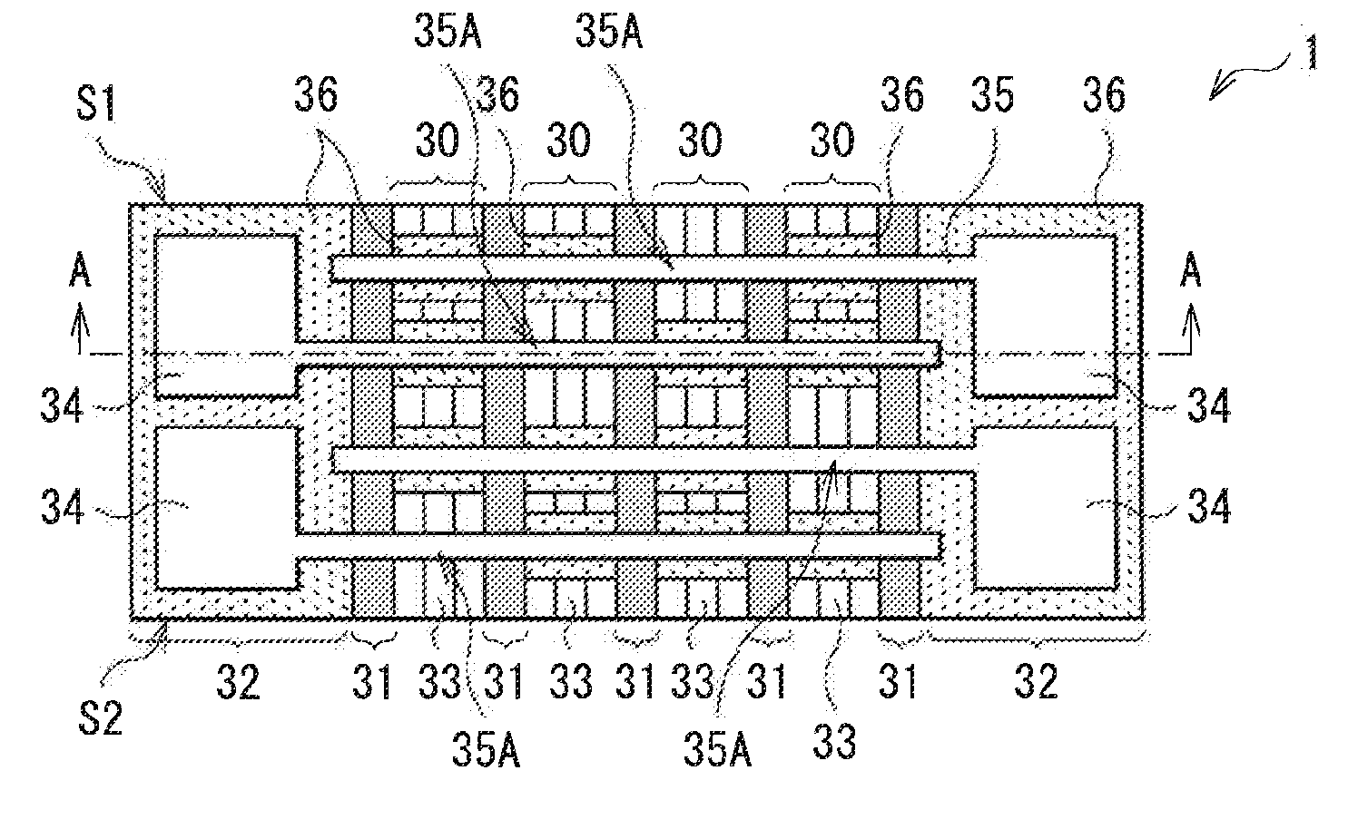
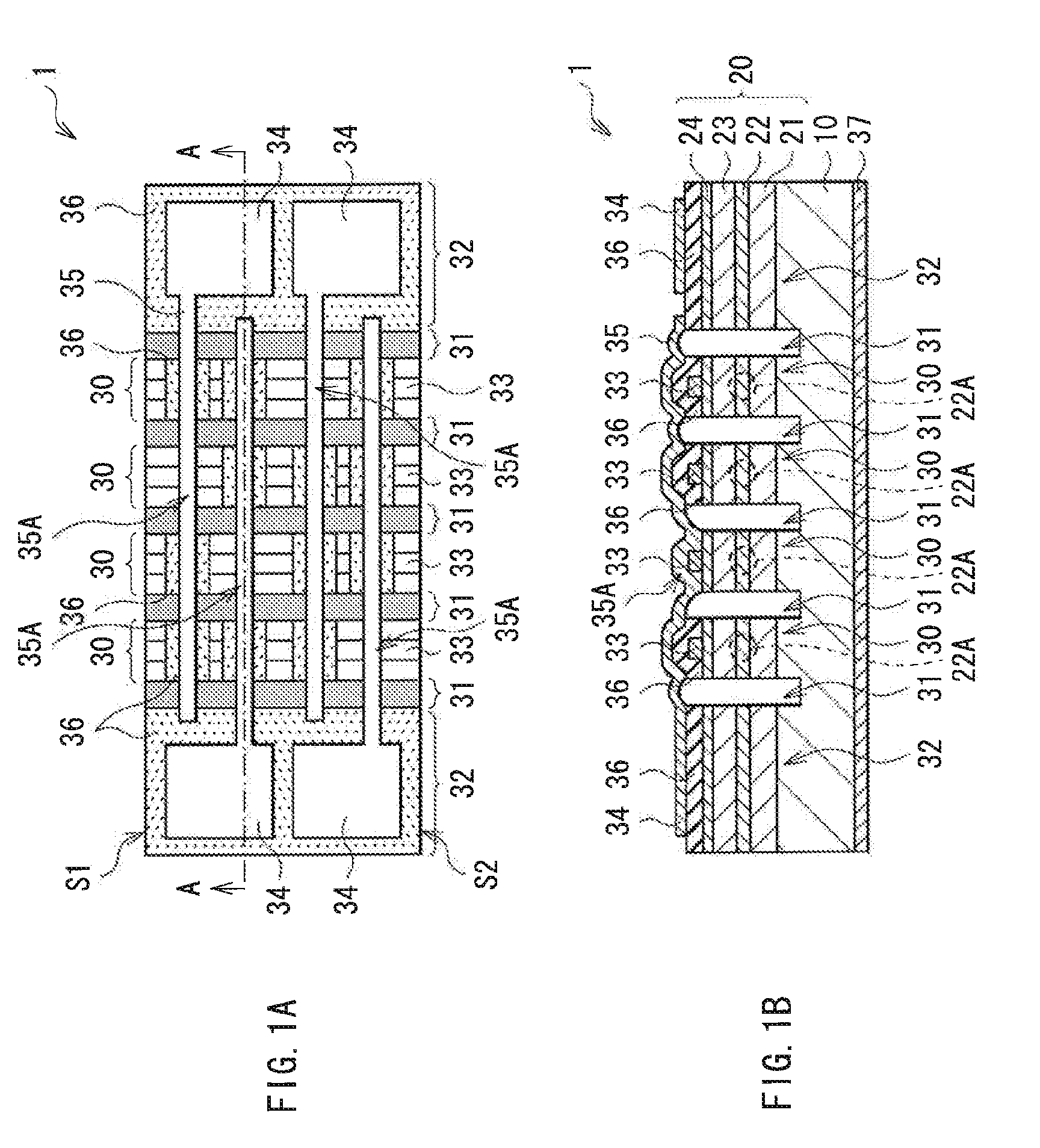
[0027]FIG. 1A illustrates an example of a top view structure of a laser diode 1 according to an embodiment of the invention. FIG. 1B illustrates an example of a cross sectional structure taken along line A-A of the laser diode 1 of FIG. 1A. The laser diode 1 of this embodiment is a multibeam laser diode including a plurality of striped emitters, and is an edge emitting laser diode in which laser beam is emitted from each end face of each emitter.

[0028]The laser diode 1 includes, for example, as illustrated in FIG. 1B, a semiconductor layer 20 including a lower cladding layer 21, an active layer 22, an upper cladding layer 23, and a contact layer 24 in this order from a substrate 10 side over the substrate 10. Thought not illustrated, the semiconductor layer 20 may be further provided with a layer other than the foregoing layers (for example, a buffer layer, a guide layer and the like). In the semiconductor layer 20, a plurality of strip-shaped ridges 30 (laser structure) are formed....

modified examples

[0057]In the foregoing embodiment, the description has been given of the case that the wiring layer 35 extends from one base 32 to another base 32. However, for example, the wiring layer 35 may have the end in the vicinity of the connection section 35A. In this case, for example, as illustrated in FIGS. 6A, 6B, 7A, and 7B, the end of the wiring layer 35 may be provided in the end of the top face of the ridge 30 or in the vicinity thereof. Further, for example, though not illustrated, it is possible that the wiring layer 35 hurdles the upper electrode 33 contacted with the wiring layer 35, and the end of the wiring layer 35 is provided in the vicinity of a side face of the upper electrode 33. Further, in the case where the end of the wiring layer 35 is provided in the end of the top face of the ridge 30 or in the vicinity thereof, or is provided in the vicinity of a side face of the upper electrode 33, for example, as illustrated in FIGS. 6A and 6B, a dummy wiring layer 35B not funct...


PUM


Abstract

A laser diode includes: a plurality of strip-shaped laser structures arranged in parallel with each other, and including a lower cladding layer, an active layer, and an upper cladding layer in this order; a plurality of strip-shaped upper electrodes singly formed on a top face of the respective laser structures, and being electrically connected to the upper cladding layer; a plurality of wiring layers being at least singly and electrically connected to one of the respective upper electrodes; and a plurality of pad electrodes formed in a region different from that of the plurality of laser structures, and being electrically connected to one of the respective upper electrodes with the wiring layer in between. The respective wiring layers have an end in a region different from a region where the respective wiring layers are contacted with the upper electrode.

Description

BACKGROUND OF THE INVENTION[0001]1. Field of the Invention[0002]The present invention relates to a laser diode with which each emitter is able to be independently driven.[0003]2. Description of the Related Art[0004]In a laser diode, for the purpose of independently driving each emitter, a separation groove that electrically separates adjacent emitters is provided between the adjacent emitters. The width of the separation groove varies according to the laser type. In the case of a narrow pitch type laser having a beam pitch of about several tens of μm, the width of the separation groove is only about several μm. Thus, in such a case, it is significantly difficult to provide a wiring layer that connects a stripe electrode on the emitter (laser structure) with both sides surrounded by separation grooves and a pad electrode formed in a location apart from the laser structure in a narrow separation groove. Thus, for example, as described in Japanese Unexamined Patent Application Publicat...

Claims


Application Information

Patent Timeline
Patent Type & Authority Applications(United States)
IPC IPC(8): H01S5/0625
CPCH01S5/0421H01S5/4031H01S5/22H01S5/0425H01S5/026H01S2301/176H01S5/04256
Inventor NAKASHIMA, MAKOTOYOKOYAMA, TAKAHIROKARINO, SACHIOTAKASE, EIJIYOSHIDA, YUTA
Owner SONY CORP
Why Eureka
Try Eureka