Dynamic accelerated reaction batteries utilizing taylor vortex flows

a technology of dynamic acceleration and reaction batteries, applied in the field of electrochemical cells and batteries, can solve the problems of no evidence that any of these cells or batteries is capable of discharging, and achieve the effects of increasing active or exposed electrode areas, enhancing ion transport through the membrane, and increasing the mass transport of ions

Active Publication Date: 2010-12-30
GLOBAL ENERGY SCI CALIFORNIA
View PDF11 Cites 9 Cited by
  • Summary
  • Abstract
  • Description
  • Claims
  • Application Information

AI Technical Summary

Benefits of technology

[0030]The present invention is a robust electrochemical cell or battery for providing electrical energy containing a fluid electrolyte between relatively rotating, co-axial cylindrical electrodes that cause Taylor Vortex Flows (TVF) and Circular Couette Flows (CCF) within the electrolyte. Where a membrane is required for separation of incompatible electrolytes, TVF and CCF enhance ion transport through the membrane.
[0031]It is therefore a first object of the present invention to provide a robust battery utilizing TVF and CCF to provide greatly increased mass transport of ions withi

Problems solved by technology

However, there is no evidence that any of these cells or batteries is capable of disch

Method used


Image

  • Dynamic accelerated reaction batteries utilizing taylor vortex flows
  • Dynamic accelerated reaction batteries utilizing taylor vortex flows
  • Dynamic accelerated reaction batteries utilizing taylor vortex flows

Examples


first embodiment

Four Cell Stack

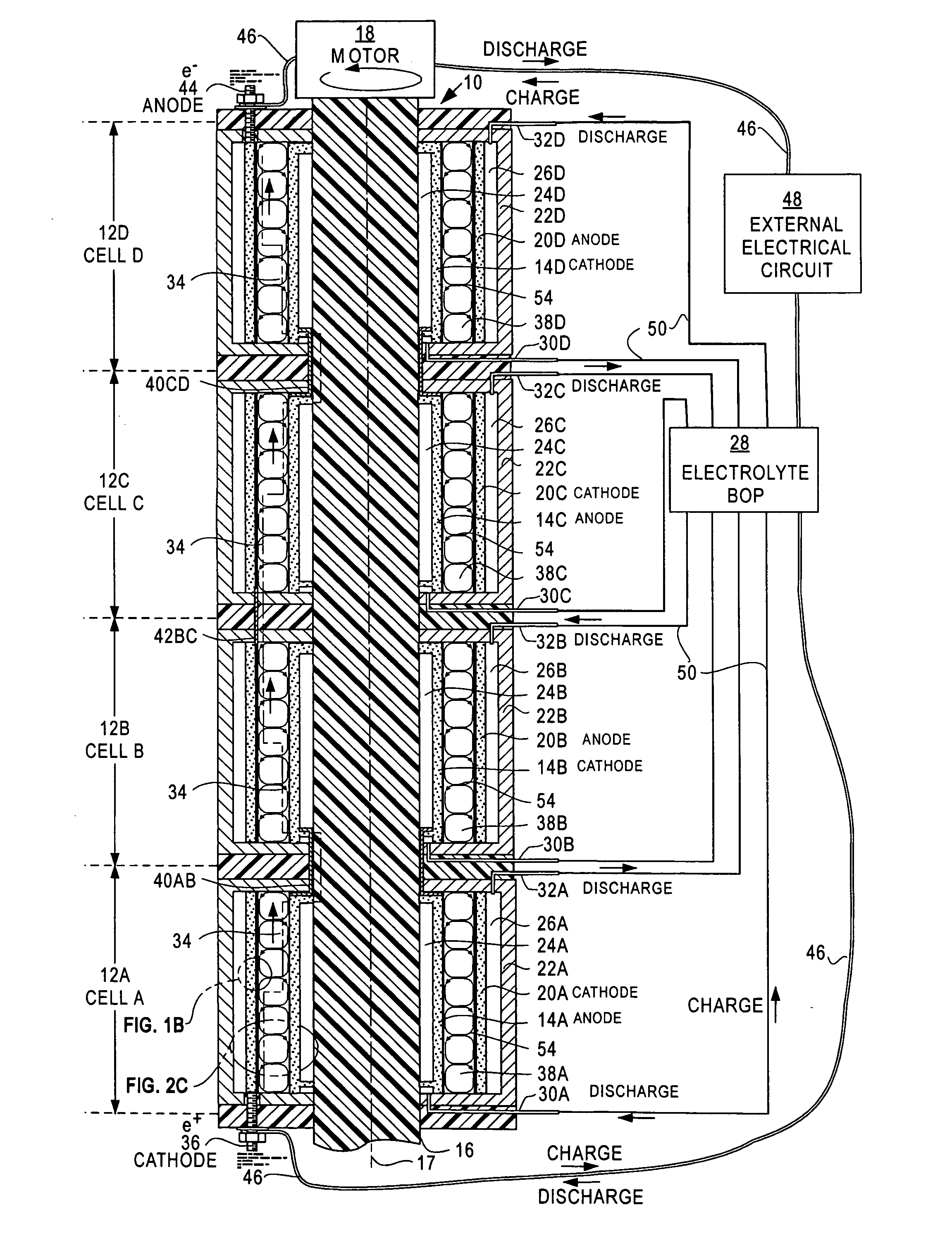
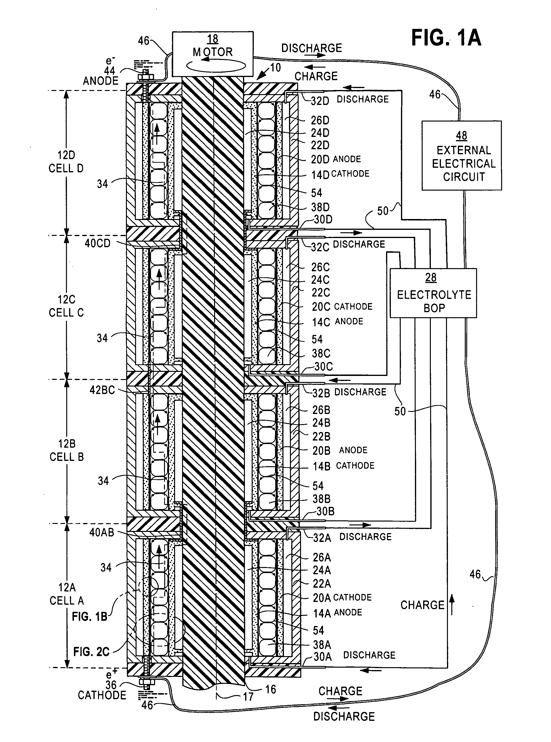
[0051]FIG. 1A is a fragmentary cross-section view of a Dynamic Accelerated Reaction Battery 10. FIG. 1A resembles FIG. 6 of Case D, which is a cross-section view of a TVF / CCF fuel cell. While the battery 10 and the fuel cell of Case D both convert their potential energies to electrical energy and share many similarities relating to TVF and CCF, they operate differently. DARB and most conventional batteries store potential energy in their electrodes or dual electrolytes while fuel cells store potential energy in their fuels. As a result, batteries and fuel cells have different energy densities, power densities, terminal voltages and currents.

[0052]The battery 10 comprises four cells CELL A —12A, CELL B —12B, CELL C —12C and CELL D —12D. Each cell contains a rotating electrode 14x where x stands for one of the letters A, B, C or D that is associated with one of the four cells 12x. The electrodes 14x are fixed to a shaft 16 that rotates about spin axis 17 and is driven b...

second embodiment

Interdigitated Electrodes

[0136]FIG. 4 is a fragmentary cross-sectional view of a second preferred embodiment of a Dynamic Accelerated Reaction Batteries (DARB) 100. The battery 100 contains two cells 102A and 102B (also identified as 102x, where x=A or B) that are connected in series, as shown for the battery 10 of FIG. 1A.

[0137]Each of the cells 102x contains a pair of interdigitated electrodes 104x structured as sets of anode 106x and cathode 108x concentric, cylinder-like electrodes. The electrodes 106x and 108x are interdigitated or nested with each other, as shown in FIG. 4. A primary advantage of interdigitated electrodes 102x is increased energy and power density per cm3 that is achieved by rotating one of the electrodes 106x, 108x relative to the other to generate TVF and CCF—as taught above for DARB 10 of FIG. 1A.

[0138]For cell 102A, the cathode electrodes 108A are ∩-shaped and secured to fixed electrode plate 109A, which provides:[0139]Mechanical support for the cathode el...

third embodiment

Membrane with Incompatible Electrolytes

[0178]FIG. 5 is a fragmentary cross-sectional view of a third preferred embodiment of a Dynamic Accelerated Reaction Battery 200, which may be used where two incompatible electrolytes (e.g., aqueous and organic) are required—such as in a nickel-lithium battery. Prior art cells and batteries use a membrane to separate the two incompatible electrolytes; however, the membrane permits ions to travel from one electrode to the other. These cells must have increased internal resistance because of low ionic permeability of their membranes. As will be described, cells and batteries of this invention incorporate membranes both to separate incompatible electrolytes and to decrease internal resistance.

[0179]DARB 200 comprise a cell 201 containing a lithium metal anode electrode 202 separated from a nickel-hydroxide cathode 204 by an electrolyte chamber 206 divided by an ion-permeable membrane 208. The membrane 208 divides the electrolyte chamber 206 into s...


PUM


Abstract

Dynamic accelerated reaction batteries (10, 100, 200) with rotating electrodes (14x, 20x, 104x, 106x,) or rotating membranes (208) or fuel cells (412C, 412D) that generate Taylor Vortex Flows (54, 122, 228, 454) and Circular Couette Flows (56, 124, 230) in electrolyte chambers (38x,126x, 206, 438x) are disclosed.

Description

CROSS-REFERENCE TO RELATED APPLICATIONS[0001]This application claims the benefit of U.S. Provisional Application No. 61 / 220,583 filed 26 Jun. 2009 by Halbert P. Fischel, which is incorporated herein by reference.[0002]This application, identified as Case E, is related to the following applications of Halbert P. Fischel:[0003]Case A: Electrochemical Cells Utilizing Taylor Vortex Flows, application Ser. No. ______;[0004]Case B: Fuel Reformers Utilizing Taylor Vortex Flows, application Ser. No. ______;[0005]Case C: Chemical Process Accelerator Systems Comprising Taylor Vortex Flows, application Ser. No. ______; and[0006]Case D: Direct Reaction Fuel Cells Utilizing Taylor Vortex Flows, application Ser. No. ______.Case A, Case B, Case C, Case D and Case E (this case) were all filed on the same day. All of these applications have been assigned to the same assignee. The other applications are incorporated herein by reference.STATEMENT REGARDING FEDERALLY SPONSORED RESEARCH OR DEVELOPMENT[0...

Claims


Application Information

Patent Timeline
IPC IPC(8): H01M8/02H01M2/38
CPCB01F7/008Y02E60/522B01J12/007B01J14/005B01J15/005B01J16/005B01J19/1806B01J19/1893B01J2219/00083B01J2219/00135C01B3/065C01B3/40C01B2203/0233C01B2203/0261C01B2203/0277C01B2203/0283C01B2203/066C01B2203/1041C01B2203/1047C01B2203/1064C01B2203/107C01B2203/1076C01B2203/1082C01B2203/1223C01B2203/1229C01B2203/1241C01B2203/1247H01M4/90H01M4/92Y02E60/362Y02E60/523Y02E60/50B01J10/007Y02P20/52Y02E60/36B01F27/272
Inventor FISCHEL, HALBERTLUBIN, PHILIP MICHAELLUBIN, DANIEL TIMOTHY
Owner GLOBAL ENERGY SCI CALIFORNIA
Why Eureka
Try Eureka