Optical analyzer

a technology of optical analyzer and optical probe, which is applied in the field of optical analyzer, can solve the problems of low signal-to-noise ratio, small invasion depth, low spatial resolution, etc., and achieve the effect of excellent spatial resolution

Inactive Publication Date: 2010-12-30
SUMITOMO ELECTRIC IND LTD
View PDF45 Cites 6 Cited by
  • Summary
  • Abstract
  • Description
  • Claims
  • Application Information

AI Technical Summary

Benefits of technology

[0006]An object of the present invention is to provide an optical analyzer capable of performing analysis excellent in spatial resolution and in invasion depth.

Problems solved by technology

The analysis using this optical analyzer may result in a low signal-to-noise ratio and a low spatial resolution.
This optical analyzer may result in a small invasion depth when measuring a measurement subject with a large elastic scattering.

Method used


Image

  • Optical analyzer
  • Optical analyzer
  • Optical analyzer

Examples


first embodiment

of Optical Analyzer

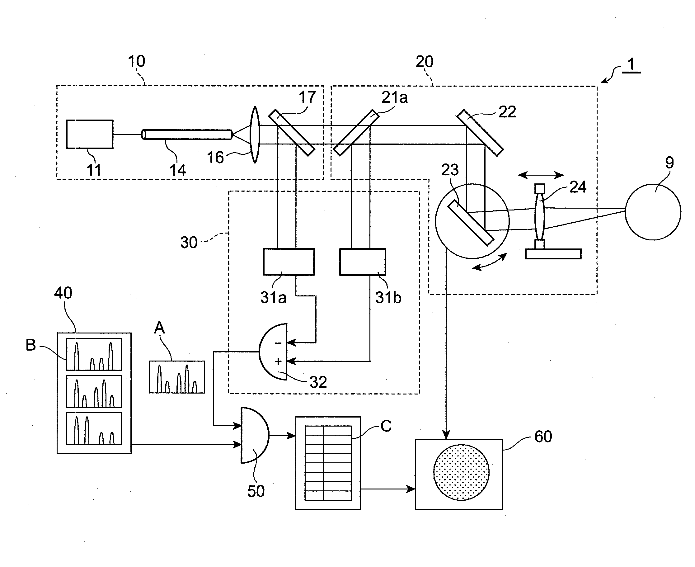
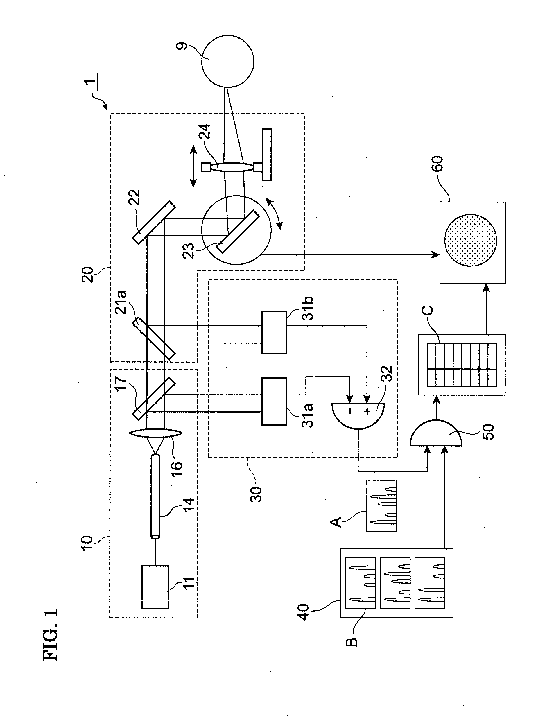
[0024]FIG. 1 is a block diagram showing a first embodiment of an optical analyzer of the present invention. An optical analyzer 1 is a device capable of identifying a measurement subject 9 and evaluating the state of a substance by measuring a loss spectrum. The optical analyzer 1 includes a diagnostic light source section 10, an optical system 20, a spectrum measurement section 30, a storage section 40, an arithmetic section 50, and a display section 60.

[0025]The diagnostic light source section 10 includes a pump pulse source 11, an optical fiber 14, a lens 16, and a semi-transparent mirror 17. A spatial density of an optical power of at least a part of the optical fiber 14 is 1 mW / μm2 or more. The diagnostic light source section 10 outputs diagnostic light having an optical power of 1 μW / nm or more at least in a part of a spectrum band ranging from 0.8 to 3.0 μm.

[0026]The pump pulse source 11 generates pump pulse light having a center wavelength λp within a wave...

second embodiment

of Optical Analyzer

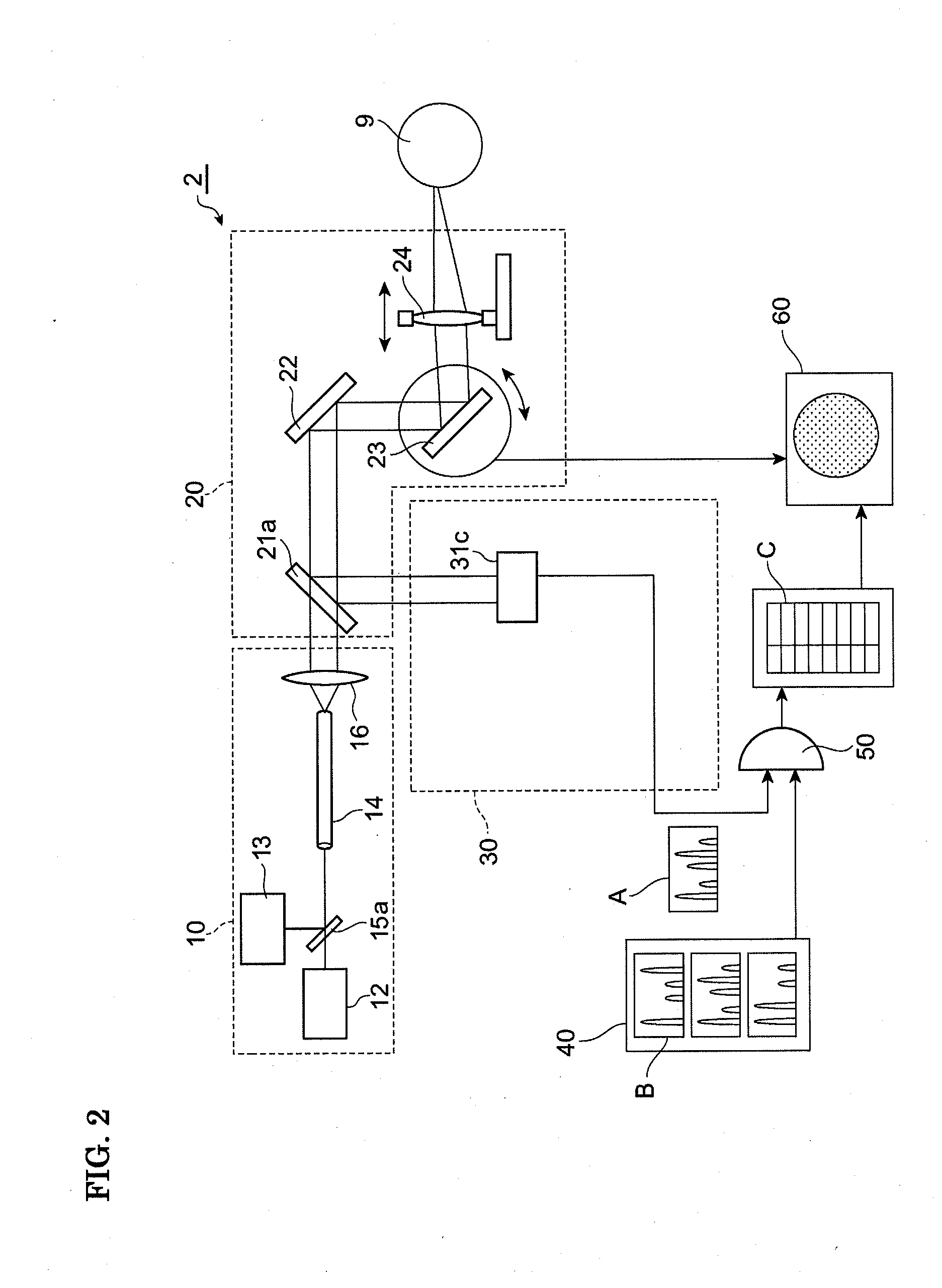
[0035]FIG. 2 is a block diagram showing a second embodiment of the optical analyzer of the present invention. An optical analyzer 2 is a device capable of identifying a measurement subject 9 and evaluating the state of a substance by measuring a Raman scattering spectrum. The optical analyzer 2 includes a diagnostic light source section 10, an optical system 20, a spectrum measurement section 30, a storage section 40, an arithmetic section 50, and a display section 60.

[0036]The diagnostic light source section 10 generates and outputs diagnostic light. The diagnostic light source section 10 includes a seed pulse source 12, a pump source 13, an optical fiber 14, a semi-transparent mirror 15a, and a lens 16. The seed pulse source 12 generates seed pulse light having a center wavelength λs within a wavelength range from 1400 to 1800 nm (more preferably, a wavelength range from 1580 to 1650 nm). The pump source 13 generates pump light having a center wavelength λp in a...

third embodiment

of Optical Analyzer

[0045]FIG. 3 is a block diagram showing a third embodiment of the optical analyzer of the present invention. An optical analyzer 3 is a device capable of identifying a measurement subject 9 and evaluating the state of a substance by measuring a loss spectrum and a Raman scattering spectrum. The optical analyzer 2 includes a diagnostic light source section 10, an optical system20, a spectrum measurement section 30, a storage section 40, an arithmetic section 50, and a display section 60.

[0046]The diagnostic light source section 10 generates and outputs first diagnostic light and second diagnostic light. The diagnostic light source section 10 includes a pump pulse source 11, a seed pulse source 12, a pump source 13, an optical fiber 14, semi-transparent mirrors 15a and 15b, a lens 16, and a semi-transparent mirror 17. In these elements, the pump pulse source 11 is similar to that of the first embodiment, and the seed pulse source 12 and the pump source 13 are simila...


PUM


Abstract

An optical analyzer performing analysis excellent in spatial resolution and in invasion depth is provided. The analyzer includes a diagnostic light source section including a seed light source which outputs seed light, and a silica optical fiber to which seed light is input and which generates diagnostic light having a HE11 mode field pattern utilizing a nonlinear optical phenomenon, an irradiation optical system converging the diagnostic light and irradiating a measurement subject with the diagnostic light, an acquisition optical system acquiring object light generated at the measurement subject, a spectrum measurement section receiving the object light and measuring a frequency spectrum of the object light, a storage section storing information of a frequency spectrum of a known substance, and an arithmetic section calculating a correspondence between the frequency spectrum of the object light and the frequency spectrum of the known substance, and analyzing the measurement subject based on the calculation result.

Description

[0001]This application claims priority to U.S. patent application Ser. No. 11 / 921,577 to Takemi Hasegawa, filed Dec. 5, 2007 entitled “Optical Analyzer,” which is a National Stage Application of International Patent Application No. PCT / JP2007 / 050672, filed Jan. 18, 2007, which claims priority to Japanese Application No. 2006-013010, filed on Jan. 20, 2006, which has issued as Japanese Patent No. 3,992,064, the contents and subject matter of each being incorporated herein by reference.TECHNICAL FIELD[0002]The present invention relates to an optical analyzer capable of identifying a measurement subject and evaluating the state of a substance by measuring an optical spectrum, and of being preferably used for sorting medicine and for examining living tissue.BACKGROUND ART[0003]Examples of known optical analyzers capable of identifying measurement subjects and evaluating the states of substances are disclosed in Patent Documents 1 and 2. The optical analyzer disclosed in Patent Document ...

Claims


Application Information

Patent Timeline
Patent Type & Authority Applications(United States)
IPC IPC(8): A61B6/00
CPCA61B5/0059B07C5/3425G01N21/65G01N21/359
Inventor HASEGAWA, TAKEMI
Owner SUMITOMO ELECTRIC IND LTD
Why Eureka
Try Eureka