Method and Device for Visualizing an Installation of Automation Systems Together with a Workpiece

a technology of automation system and workpiece, which is applied in the direction of program control, total factory control, instruments, etc., can solve the problems of additional restrictions to degrees of freedom

Active Publication Date: 2010-12-30
SIEMENS AG
View PDF13 Cites 6 Cited by
  • Summary
  • Abstract
  • Description
  • Claims
  • Application Information

AI Technical Summary

Benefits of technology

[0012]An advantage of the method in accordance with the invention is that the user can directly monitor the workpiece that is to be processed by the automated system and, for example, can track the process steps that are performed on the workpiece by the system. As a result, the aforementioned control program can be tested in advance in relation to the control processes implemented therein for the individual production steps that are to be performed on the workpiece by the automated system. Ultimately, testing in this manner leads to a control program that has been tested such that it needs to be tested far less thoroughly after it is implemented in the actual automated system upon completion of the test phase, with the result that in certain cases the downtimes and test times on the real automated system can be significantly shortened.
[0028]A device in accordance with an embodiment of the invention provides the user with a simple and intuitive way to monitor a workpiece in a 3D visualization of an automated system. The individual process steps that are performed on the workpiece within the automated system can also be monitored. Here, the user can adjust the view onto the workpiece such that he / she has the workpiece in an unobscured view and in a suitable size on the screen and together with the important system components. Accordingly, owing to the workpiece-centered and workpiece-tracking visualization, the device offers in a suitable and intuitive manner the possibility to track and simulate processes that are performed on the workpiece in the system. In particular, the tracking of an individual workpiece is very well suited to the verification of the control flows in an automation system and consequently also for testing the aforementioned control program.

Problems solved by technology

Furthermore, there are combinations of the cited navigation possibilities or modifications which result from additional restrictions to degrees of freedom.

Method used


Image

  • Method and Device for Visualizing an Installation of Automation Systems Together with a Workpiece
  • Method and Device for Visualizing an Installation of Automation Systems Together with a Workpiece
  • Method and Device for Visualizing an Installation of Automation Systems Together with a Workpiece

Examples


Embodiment Construction

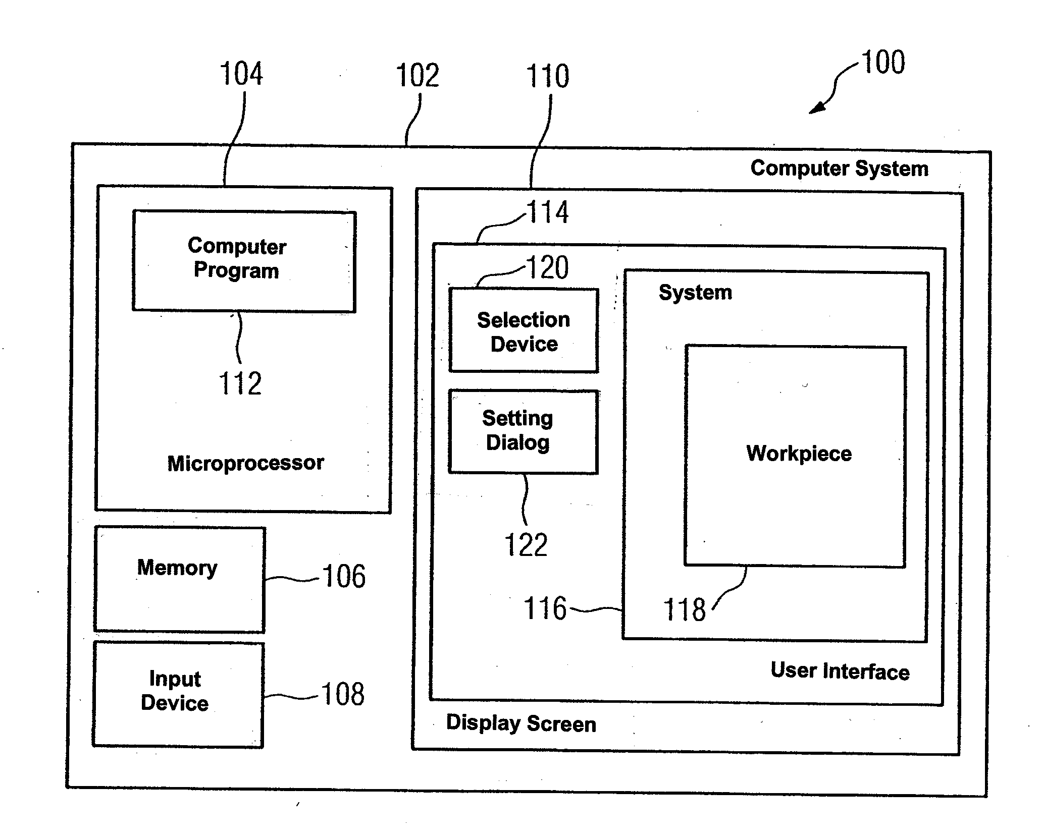
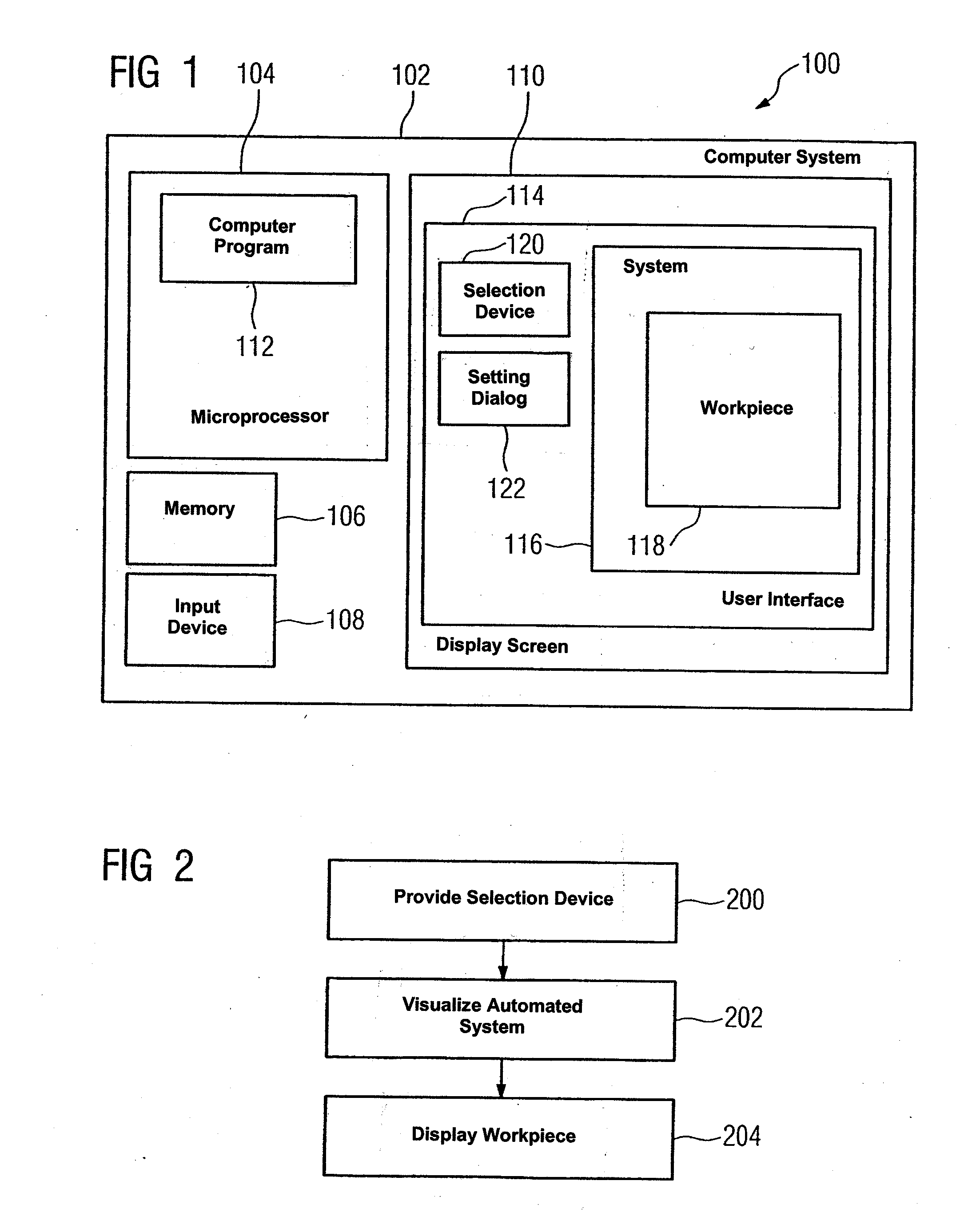
[0038]FIG. 1 is an illustration of a schematic block diagram of a device 100 for visualizing a workpiece of an automated system. The device 100 comprises a computer system 102. The computer system 102 has a microprocessor 104, a memory 106, an input device 108 and a display screen 110.

[0039]The microprocessor 104 executes a computer program 112 which is permanently resident in the memory 106 and has been read out of the memory 106 by the microprocessor 104 for execution of the computer program. The computer program 112 serves for visualizing an automated system having a workpiece and generates on the display screen 110 a user interface 114 having selection device 120 and a setting dialog 122. The system 116 that is to be visualized is also presented within the user interface 114 on the display screen 110 by the computer program 112. The selection device 120 can be used by a user of the computer system 102 to select a workpiece 118 that is disposed within the automated system 116. Th...


PUM


Abstract

A method and a device for visualizing a workpiece in a visualized model of an automated installation. In accordance with the invention, the method comprises making available a selection device to the user of the visualized model of the automated installation, visualizing the automated installation together with the workpiece and centering the workpiece in the visualized model of the automated installation, where the selection device is used by the user to preselect the workpiece.

Description

CROSS-REFERENCE TO RELATED APPLICATIONS[0001]This is a U.S. national stage of International Application No. PCT / EP2008 / 000781, filed on 31 Jan. 2008.BACKGROUND OF THE INVENTION[0002]1. Field of the Invention[0003]The invention relates in general to a method and a device for visualizing an automation system having a workpiece and, more particularly, to a method and a device for visualizing an automation system containing a workpiece, the workpiece being displayed centered in the visualization.[0004]2. Description of Related Art[0005]Automated installations or, as the case may be, automation systems are deployed in a multiplicity of applications, such as in the production of mass-produced goods. An automated system and the process steps executing in the automated system, which are performed on individual workpieces requiring processing, for example, are controlled by a control program and for example a Programmable Logic Controller (PLC) programmed therewith. Simulations comprising vi...

Claims


Application Information

Patent Timeline
Patent Type & Authority Applications(United States)
IPC IPC(8): G06F19/00G06F3/048
CPCG05B19/41885Y02P90/02
Inventor HEUSCHMANN, CHRISTIANSTOLPER, THILOWALTER, DIETER
Owner SIEMENS AG
Why Eureka
Try Eureka