Method of Estimating Pulse Response Using an Impedance Spectrum

a pulse response and impedance spectrum technology, applied in the direction of instruments, electrochemical generators, spectral/fourier analysis, etc., can solve the problem of lower resolution of impedance spectra than desired, and achieve the effect of fast summation transformation and lower resolution

Active Publication Date: 2010-12-30
BATTELLE ENERGY ALLIANCE LLC
View PDF27 Cites 24 Cited by
  • Summary
  • Abstract
  • Description
  • Claims
  • Application Information

AI Technical Summary

Benefits of technology

[0010]The Fourier coefficients of the desired pulse profile are first used to establish the frequency range of the impedance measurement. For example, the period of the lowest frequency for the impedance measurement should be less than or equal to the period of the pulse profile. The maximum frequency of the impedance measurement should be greater than or equal to the largest desired harmonic value used in the Fourier coefficients used to recreate the desired pulse profile.
[0011]Knowing the desired frequency range, the ESD impedance spectrum can then be measured using any available methodology. For rapid, in-situ applications, techn

Problems solved by technology

In some cases (e.g., with Fast Summation Transformation), the impedance spectra w

Method used


Image

  • Method of Estimating Pulse Response Using an Impedance Spectrum
  • Method of Estimating Pulse Response Using an Impedance Spectrum
  • Method of Estimating Pulse Response Using an Impedance Spectrum

Examples


Embodiment Construction

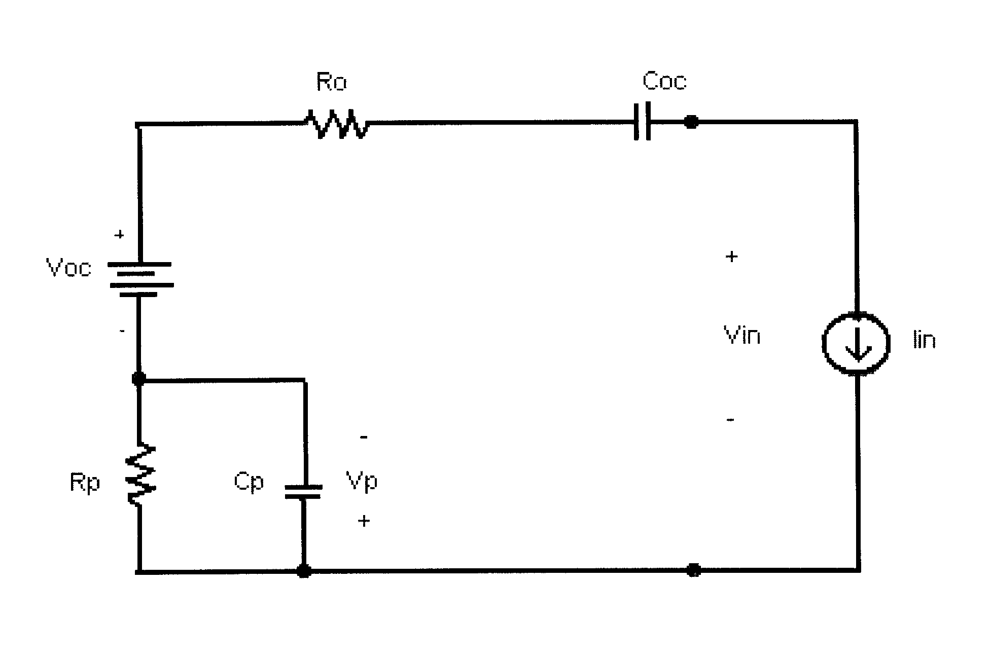
[0022]The method of the subject invention uses wideband impedance measurements to predict the response of an energy storage device (ESD) to a pulse excitation. The impedance spectrum can be acquired by various methods, but rapid, in-situ techniques such as Fast Summation Transformation (FST) are preferred. FST is based on a computationally simple approach, and it only requires one period of the lowest frequency to complete a measurement (Morrison, 2009).

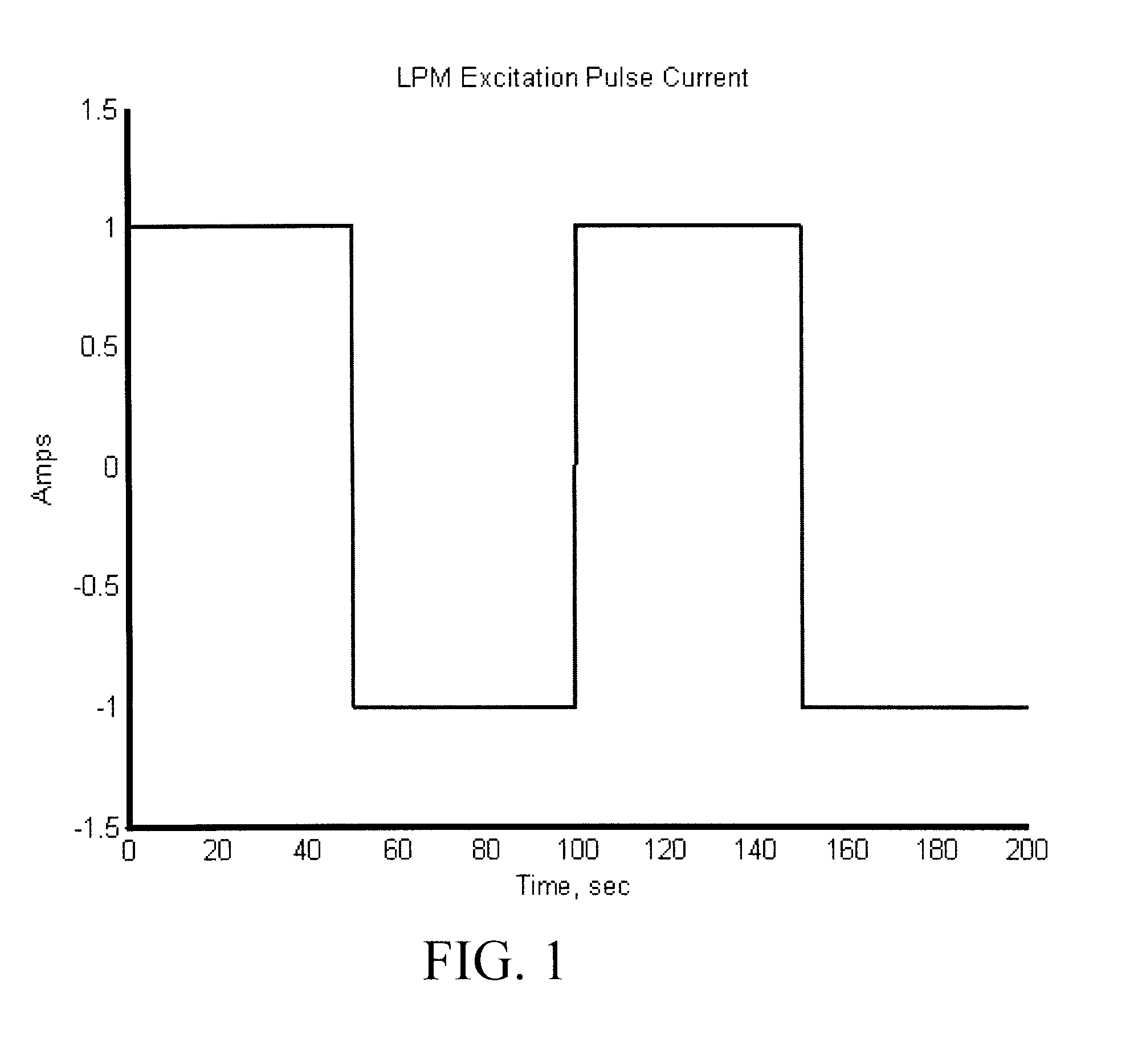
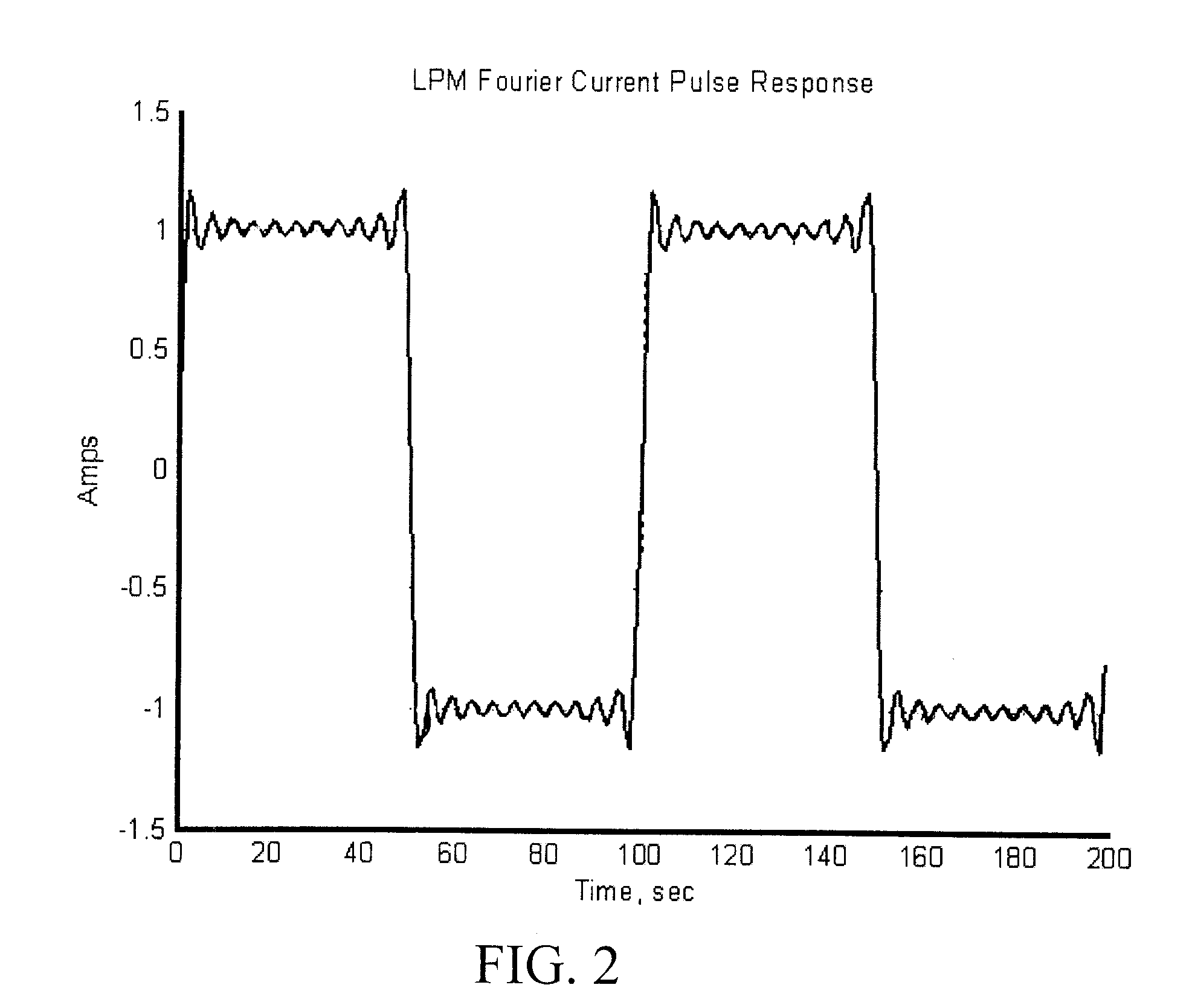
[0023]In a preferred embodiment, the anticipated or desired excitation pulse consists of a constant current square-wave profile. If it assumed that this profile is periodic (for analysis purposes only), the waveform can be decomposed into the constituent harmonic components using Fourier series methods. An example of an excitation pulse is shown in FIG. 1 and described by Equation 1, where a constant current pulse (i.e., IP) is applied for a discharge (i.e., +IP) and charge (i.e., −IP) step over two periods with T0 set to one half th...


PUM


Abstract

Electrochemical Impedance Spectrum (EIS) data are used directly to predict the pulse performance of an energy storage device. The impedance spectrum of the EIS is obtained in-situ using pre-existing techniques. A simulation waveform is configured such that the period of the pulse is greater than or equal to the lowest frequency of the impedance measurement. If the pulse is assumed to be periodic for analysis purposes, the complex Fourier series coefficients can be obtained. The number of harmonic constituents are selected so as to appropriately resolve the response, but the maximum frequency should be less than or equal to the highest frequency of the impedance measurement. In some cases, the measured frequencies of the impedance spectrum do not match the corresponding harmonic components of the simulated pulse wave. This is resolved by estimating the impedance measurements at the desired frequencies using linear interpolation, cubic spline fits, or other comparable methods. Using a current pulse as an example, the Fourier coefficients of the pulse are multiplied by the impedance spectrum at the corresponding frequency to obtain the Fourier coefficients of the voltage response to the desired pulse. The Fourier coefficients of the response are then summed reassemble to obtain the overall time domain estimate of the voltage using the Fourier series analysis. Thus, the response of an energy storage device to an anticipated or desired pulse can be estimated using low-level, charge neutral impedance measurements combined with Fourier series analysis.

Description

CROSS-REFERENCE TO RELATED APPLICATIONS[0001]This application claims the benefits of U.S. Provisional Patent Application No. 61 / 186,358; filed Jun. 11, 2009. The disclosure of this application is hereby incorporated by reference in its entirety, including all figures, tables and drawings.STATEMENT REGARDING FEDERALLY SPONSORED RESEARCH OR DEVELOPMENT[0002]This invention was made with government support under Grant No. DE-AC07-05ID14517 awarded by the United States Department of Energy. The government has certain rights in the invention.REFERENCE TO SEQUENCE LISTING, A TABLE, OR A COMPUTER PROGRAM LISTING COMPACT DISC APPENDIX[0003]Not Applicable.BACKGROUND OF THE INVENTION[0004]Energy storage devices (e.g., batteries, fuel cells, ultracapacitors, etc.) have become significantly more prevalent in many government and commercial applications (e.g., automotive, military, space, electric utilities, medical, etc.). Consequently, there has also been an increased interest in smart monitorin...

Claims


Application Information

Patent Timeline
IPC IPC(8): G01R23/16G01R31/36G06F19/00
CPCH01M10/0525G01R31/3662G01R31/389Y02E60/10
Inventor MORRISON, JOHN L.MORRISON, WILLIAM H.CHRISTOPHERSEN, JON P.MOTLOCH, CHESTER G.
Owner BATTELLE ENERGY ALLIANCE LLC
Why Eureka
Try Eureka