
Analytical bandwidth enhancement for monitoring telemetric signals

Active Publication Date: 2010-12-30
ORACLE INT CORP
View PDF1 Cites 2 Cited by
  • Summary
  • Abstract
  • Description
  • Claims
  • Application Information

AI Technical Summary

Benefits of technology

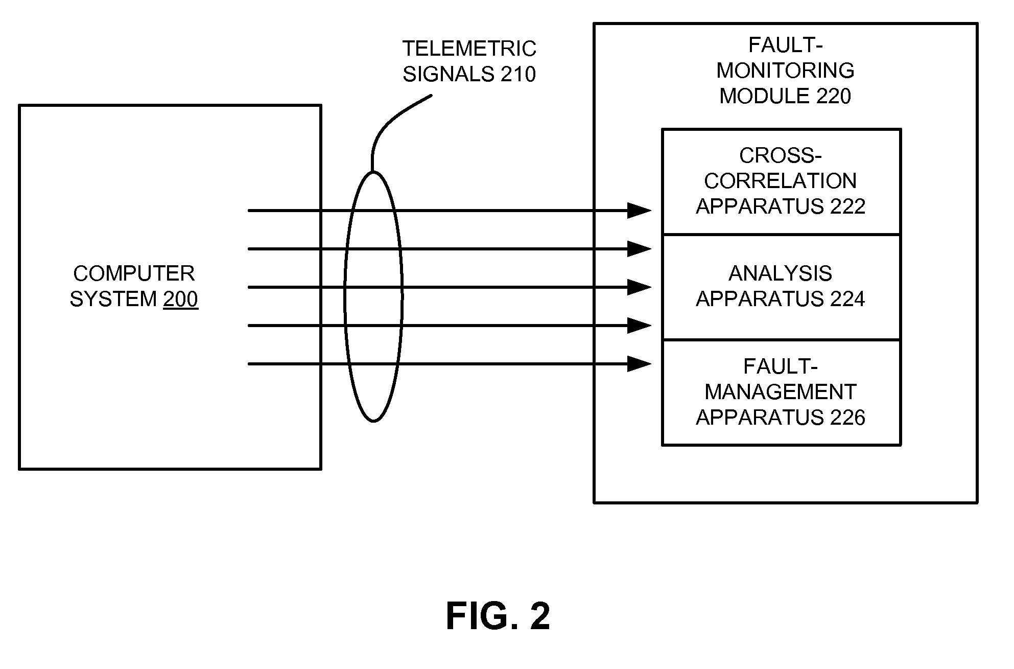
[0010]Some embodiments provide a system that analyzes telemetry data from a monitored system. During operation, the system obtains the telemetry data as a set of telemetric signals from the monitored system and groups the telemetry data into one or more clusters of correlated telemetric signals from the telemetric signals. Next, the system increases a bandwidth

Problems solved by technology

A failure in one of these enterprise computing systems can be disastrous, potentially resulting in millions of dollars of lost business.
More importantly, a failure can seriously undermine consumer confidence in a business, making customers less likely to purchase goods and services from the business.
If systems perform too little event monitoring, when a problem crops up at a customer site, service engineers may be unable to quickly identify the source of the problem.
This can lead to increased down time.
In turn, the use of additional sensors to collect telemetry data at high sampling rates has resulted in higher bandwidth demands associated with sampling the telemetry data.
However, system buses that collect and transmit the telemetry data typically have bandwidth limitations that prevent the telemetry data from being sampled beyond a certain rate.
As a result, an increase in sensor density within a computer server may cause the sampling rate of one or more sensors to fall.
For example, a computer server with an I2C system bus and thousands of sensors may be so bandwidth-limited that each sensor may only be sampled once a minute or longer.
Dynamic monitoring and integrity analysis techniques that require frequent sampling of sensors may thus be impeded by such slow sampling rates.

Method used


Image

  • Analytical bandwidth enhancement for monitoring telemetric signals
  • Analytical bandwidth enhancement for monitoring telemetric signals
  • Analytical bandwidth enhancement for monitoring telemetric signals

Examples


Embodiment Construction

[0024]The following description is presented to enable any person skilled in the art to make and use the embodiments, and is provided in the context of a particular application and its requirements. Various modifications to the disclosed embodiments will be readily apparent to those skilled in the art, and the general principles defined herein may be applied to other embodiments and applications without departing from the spirit and scope of the present disclosure. Thus, the present invention is not limited to the embodiments shown, but is to be accorded the widest scope consistent with the principles and features disclosed herein.

[0025]The data structures and code described in this detailed description are typically stored on a computer-readable storage medium, which may be any device or medium that can store code and / or data for use by a computer system. The computer-readable storage medium includes, but is not limited to, volatile memory, non-volatile memory, magnetic and optical...


PUM


Abstract

Some embodiments provide a system that analyzes telemetry data from a monitored system. During operation, the system obtains the telemetry data as a set of telemetric signals from the monitored system and groups the telemetry data into one or more clusters of correlated telemetric signals from the telemetric signals. Next, the system increases a bandwidth associated with monitoring the telemetric signals. To increase the bandwidth, the system omits one or more of the correlated telemetric signals from each of the clusters during sampling of the telemetric signals and estimates the omitted correlated telemetric signals by applying a nonlinear, nonparametric regression technique to the sampled telemetric signals.

Description

BACKGROUND[0001]1. Field[0002]The present embodiments relate to techniques for analyzing telemetry data. More specifically, the present embodiments relate to a method and system for enhancing bandwidth associated with sampling telemetric signals from a monitored system.[0003]2. Related Art[0004]As electronic commerce becomes more prevalent, businesses are increasingly relying on enterprise computing systems to process ever-larger volumes of electronic transactions. A failure in one of these enterprise computing systems can be disastrous, potentially resulting in millions of dollars of lost business. More importantly, a failure can seriously undermine consumer confidence in a business, making customers less likely to purchase goods and services from the business. Hence, it is important to ensure high availability in such enterprise computing systems.[0005]To achieve high availability, it is necessary to be able to capture unambiguous diagnostic information that can quickly locate fau...

Claims


Application Information

Patent Timeline
IPC IPC(8): G06F15/00G06F17/18
CPCG06F13/00G06F11/0748G06F11/0724G06F11/0751G06F11/0793G06F11/3055G06F11/3058G06F11/3452G06F11/3031G06F11/3096H04N19/00
Inventor HAAG, STANLEY P.BOUGAEV, ANTON A.URMANOV, ALEKSEY M.ZWINGER, STEVEN F.GROSS, KENNY C.
Owner ORACLE INT CORP
Learn More