Gas turbine component and a method for producing a gas turbine component

Inactive Publication Date: 2011-01-06
VOLVO AERO CORP
View PDF7 Cites 56 Cited by
  • Summary
  • Abstract
  • Description
  • Claims
  • Application Information

AI Technical Summary

Benefits of technology

[0018]According to a further preferred embodiment, the connection device comprises at least one bracket positioned between the strut and the fairing and that the connection element is adapted to clamp the bracket to one of the strut and the fairing. This leads to a secure and reliabl

Problems solved by technology

Casting large components with high demand on accuracy is expensive.
However, the welding implies some limitations in the production and in the shape of the component parts due to the fact that the

Method used


Image

  • Gas turbine component and a method for producing a gas turbine component
  • Gas turbine component and a method for producing a gas turbine component
  • Gas turbine component and a method for producing a gas turbine component

Examples


Embodiment Construction

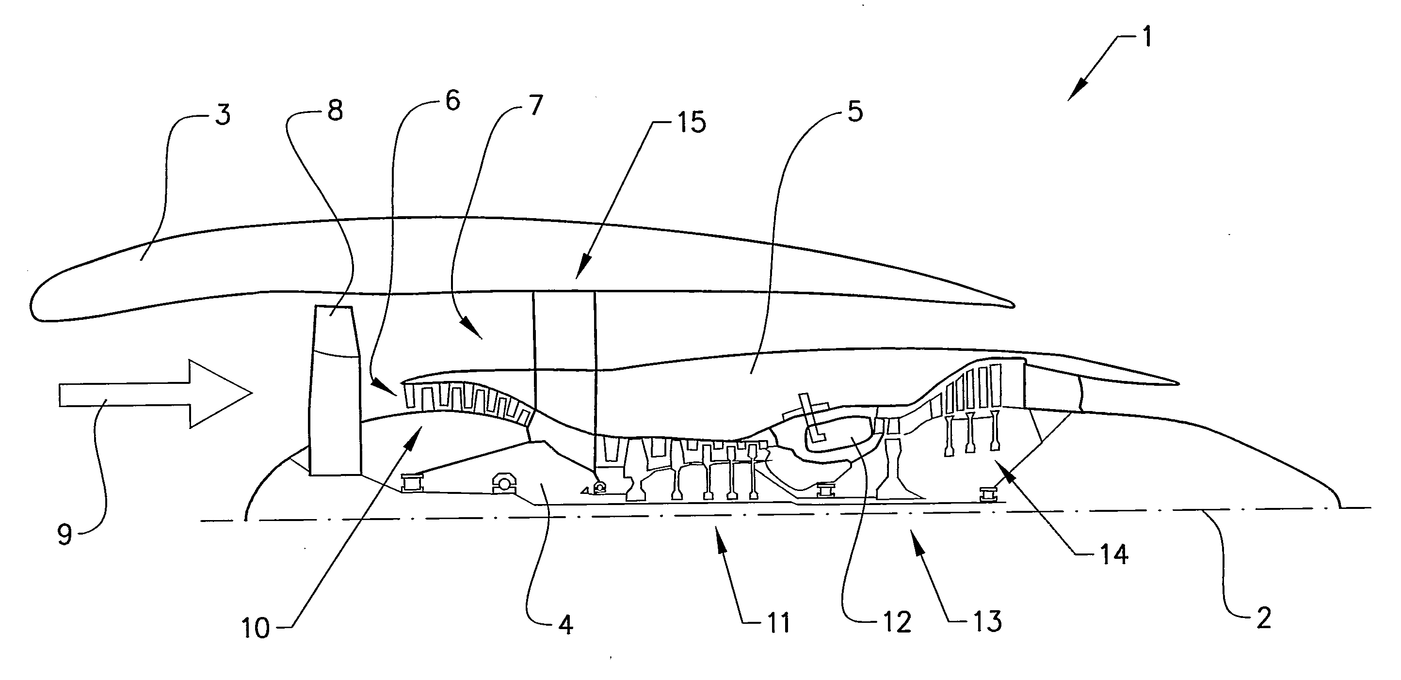
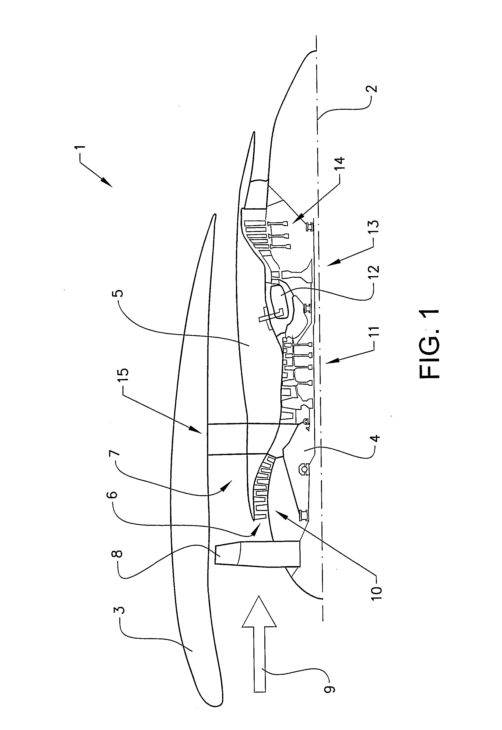
[0032]The invention will below be described for a two-shaft turbofan gas turbine aircraft engine 1, which in FIG. 1 is circumscribed about an engine longitudinal central axis 2. The engine 1 comprises an outer casing or nacelle 3, an inner casing 4 (rotor) and an intermediate casing 5 which is concentric to the first two casings and divides the gap between them into an inner primary gas channel 6 for the compression of air and a secondary channel 7 in which the engine bypass air flows. Thus, each of the gas channels 6,7 is annular in a cross section perpendicular to the engine longitudinal central axis 2.

[0033]The engine 1 comprises a fan 8 which receives ambient air 9, a booster or low pressure compressor (LPC) 10 and a high pressure compressor (HPC) 11 arranged in the primary gas channel 6, a combustor 12 which mixes fuel with the air pressurized by the high pressure compressor 11 for generating combustion gases which flow downstream through a high pressure turbine (HPT) 13 and a ...


PUM

PropertyMeasurementUnit
Distanceaaaaaaaaaa

Abstract

A gas turbine component includes an inner ring, an outer ring, and a plurality of circumferentially spaced struts which are rigidly connected to the inner ring and the outer ring forming a load-carrying structure. The component includes at least one fairing connected to two adjacent struts defining a gas channel between the struts and the fairing.

Description

BACKGROUND AND SUMMARY[0001]The present invention relates to a gas turbine component comprising a load-carrying structure, wherein the structure comprises a plurality of circumferentially spaced struts. The invention is further directed to a gas turbine engine, and especially to an aircraft engine, comprising the component. Thus, the invention is especially directed to a jet engine. The invention is further directed to a method for producing a gas turbine component.[0002]Jet engine is meant to include various types of engines, which admit air at relatively low velocity, heat it by combustion and shoot it out at a much higher velocity. Accommodated within the term jet engine are, for example, turbojet engines, turbofan and turboprop engines. The invention will below be described for a turbofan engine, but may of course also be used for other engine types.[0003]An aircraft gas turbine engine of the turbofan type with two shafts generally comprises a forward fan and booster compressor,...

Claims


Application Information

Patent Timeline
IPC IPC(8): F02C7/20B23P15/04
CPCF01D9/041Y10T29/4932F01D25/162
Inventor RUSSBERG, DAVID
Owner VOLVO AERO CORP
Why Eureka
Try Eureka