Fluorescence observation apparatus

a fluorescence observation and apparatus technology, applied in the direction of luminescent dosimeters, instruments, optical radiation measurement, etc., can solve the problem that the fluorescence image of the residue cannot be sufficiently removed from the fluorescence image in a wavelength band

Active Publication Date: 2011-01-06
OLYMPUS CORP
View PDF1 Cites 35 Cited by
  • Summary
  • Abstract
  • Description
  • Claims
  • Application Information

AI Technical Summary

Benefits of technology

[0017]According to the present invention, an advantage is afforded in that the state of an examination site can be clearly observed by sufficiently suppressing the influence of residues.

Problems solved by technology

However, since the spectra of the residues vary between individuals and greatly depend on the color etc. of food ingested before examination, a wavelength band that is characteristic of the residues cannot be identified simply, and thus, a fluorescence image of the residues cannot be sufficiently removed from a fluorescence image in a wavelength band that depends on a lesion.

Method used


Image

  • Fluorescence observation apparatus
  • Fluorescence observation apparatus
  • Fluorescence observation apparatus

Examples


Embodiment Construction

[0032]A fluorescence observation apparatus 1 according to one embodiment of the present invention will be described below with reference to FIGS. 1 to 6.

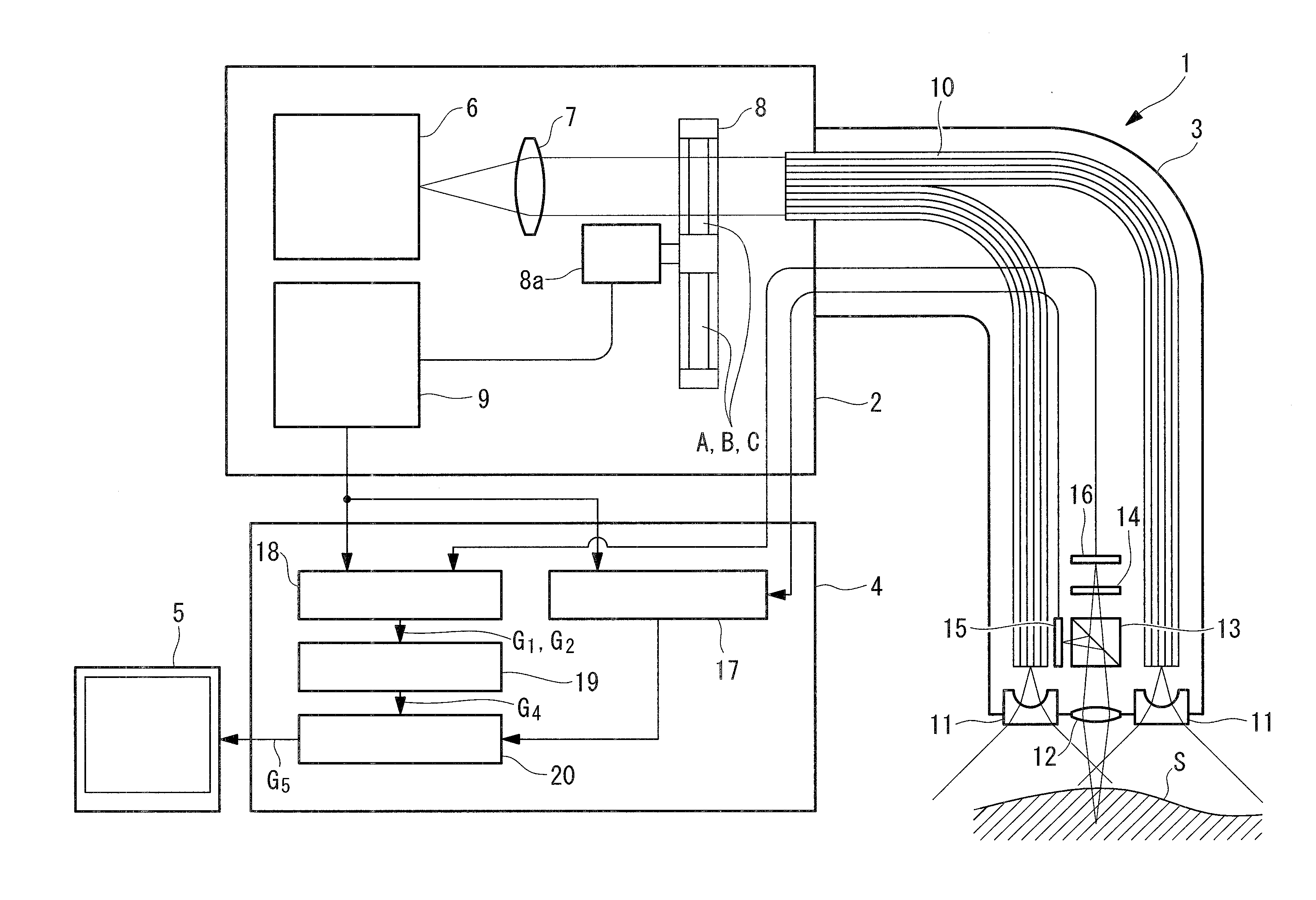
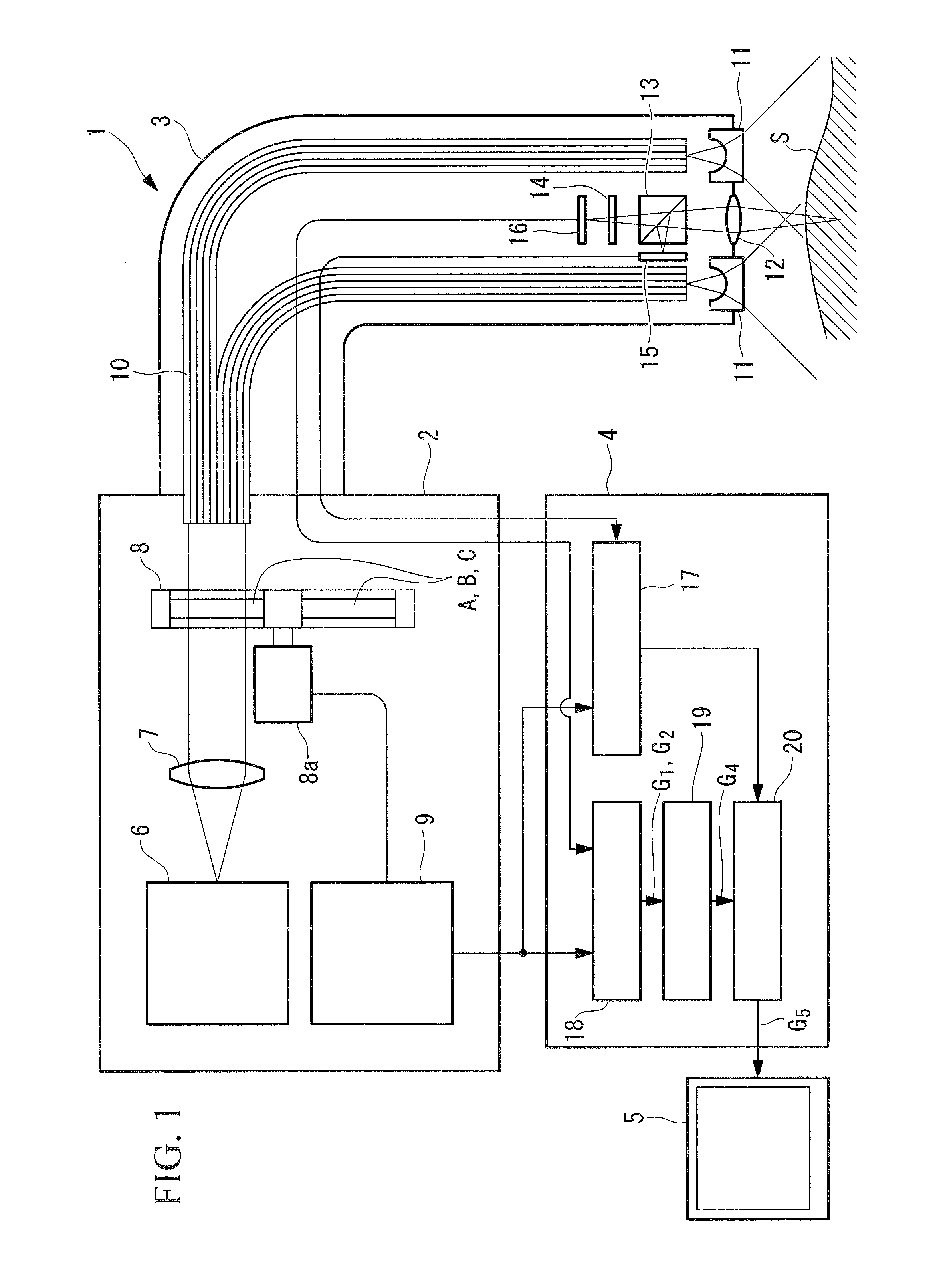
[0033]As shown in FIG. 1, the fluorescence observation apparatus 1 according to this embodiment includes a light source section 2, an insertion section 3, an image processing section 4, and a monitor 5.

[0034]The light source section 2 includes a white light source 6 that emits white light, a collimator lens 7 that converts the white light from the white light source 6 into approximately collimated light, a rotary filter 8 that extracts light in a predetermined wavelength band from the white light, and a filter controller 9 that controls the rotary filter 8.

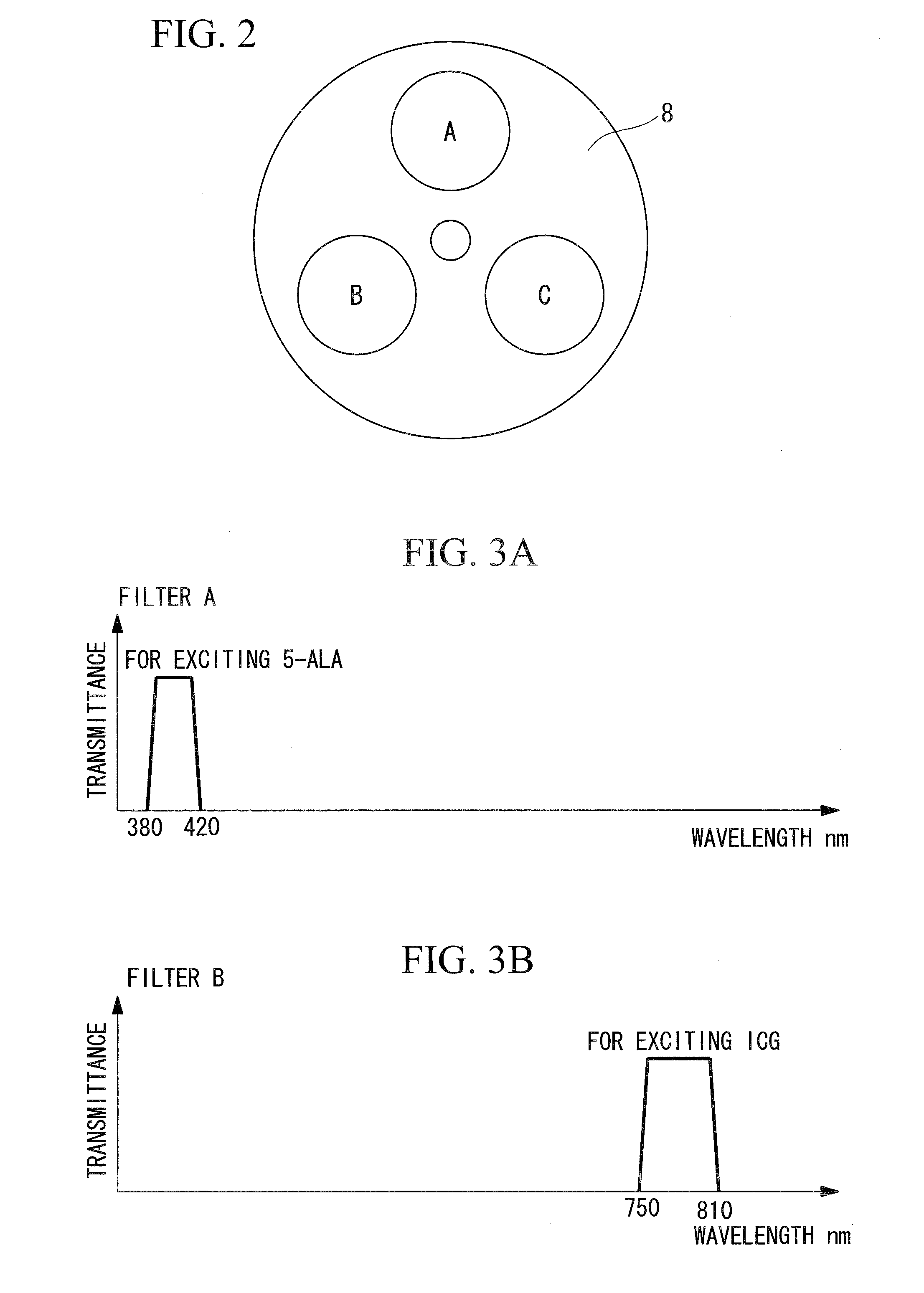
[0035]As shown in FIG. 2, the rotary filter 8 is provided with three different filters A, B, and C. As shown in FIGS. 3A to 3D, the filters A, B, and C have transmittance characteristics such that the filter A transmits light in a wavelength band from 380 nm to 420 nm for exciting...


PUM


Abstract

Clearly observing the state of an examination site is made by sufficiently suppressing the influence of residues. Fluorescence observation apparatus includes: a light source emits excitation light for irradiating the vicinity of an examination site; a fluorescence information acquisition unit acquires information about fluorescence emitted from the vicinity of the examination site through the irradiation with the excitation light from the light source; a residue fluorescence information acquisition unit acquires information about fluorescence emitted from residues selectively dyed with a fluorescent dye, through the irradiation with the excitation light from the light source; and a fluorescence information correction unit generates fluorescence information about the examination site in which the fluorescence from the residues is suppressed, based on the fluorescence information from the vicinity of the examination site, acquired by the fluorescence information acquisition unit, and the fluorescence information from the residues, acquired by the residue fluorescence information acquisition unit.

Description

CROSS-REFERENCE TO RELATED APPLICATIONS[0001]1. Technical Field[0002]The present invention relates to a fluorescence observation apparatus.[0003]This application is based on Japanese Patent Application No. 2008-076339, the content of which is incorporated herein by reference.[0004]2. Background Art[0005]A conventionally known observation apparatus acquires fluorescence in a wavelength band that is characteristic of residues (such as stool remaining in the large intestine and food being digested in the stomach) and fluorescence in a wavelength band that depends on a lesion in order to remove the influence of such fluorescence emitted from the residues from image information about fluorescence emitted through irradiation with excitation light (for example, see Japanese Unexamined Patent Application, Publication No. 2003-339623).DISCLOSURE OF INVENTION[0006]However, since the spectra of the residues vary between individuals and greatly depend on the color etc. of food ingested before e...

Claims


Application Information

Patent Timeline
Patent Type & Authority Applications(United States)
IPC IPC(8): G01J1/58
CPCA61B1/00009A61B1/041A61B1/043A61B1/045A61B1/05G01N2021/6484A61B1/0646A61B5/0071A61B5/0084G01N21/55G01N21/6456A61B1/0638A61B1/000094
Inventor ISHIHARA, YASUSHIGE
Owner OLYMPUS CORP
Why Eureka
Try Eureka