A separation device

a separation device and separation chamber technology, applied in the direction of liquid separation, centrifuges, sedimentation settling tanks, etc., can solve the problems of difficult breakage, difficult separation, and difficulty in separation of immiscible liquids, and the known separators, whether cyclones or centrifuges, suffer from lack of flexibility

Inactive Publication Date: 2011-01-06
SPECIALIST PROCESS TECH
View PDF10 Cites 34 Cited by
  • Summary
  • Abstract
  • Description
  • Claims
  • Application Information

AI Technical Summary

Problems solved by technology

The separation of immiscible liquids is particularly challenging, especially when their densities differ only slightly.
If such stable emulsions form, they can be very difficult to break in order to enable separation of the two liquid phases of the emulsion.
Known separators, whether cyclones or centrifuges, suffer from a lack of flexibility.
Consequently, they are unable to process incoming mixtures adequately at variable flow rates, or where the parameters of the incoming mixture change.
For example, known separators are often unable to separate mixtures adequately where the ratio of different fluid components changes.
In addition, solid components of incoming mixtures have a tendency to accumulate within the separators, which are unable to “self-clean”.
Consequently, solids deposits build up over time, requiring the separator to be taken off-line for cleaning purposes.
Known separators often do not work adequately in a pressurized system, or require pumps to pressurize the fluids being processed.
In cyclone separators, the rotational velocity of the fluid within the separator is uncontrolled, and such changes in rotational velocity can upset the efficiency of separation of immiscible liquids.
The requirement for centrifuges to rotate at high speed imposes a limitation on their size and capacity.
The lack of control in cyclones and centrifuges makes it difficult or impossible to vary the residence time within the unit of individual components of the original mixture.
Current separators cannot easily be retro-fitted into existing processes as used, for example, in the oil and gas production industry to replace internal components on tail end production, where the liquids to be processed contain water.
The current technology also has inadequate performance in the treatment and removal of sulphur species (sweetening) from crude oil.

Method used


Image

  • A separation device
  • A separation device
  • A separation device

Examples


Embodiment Construction

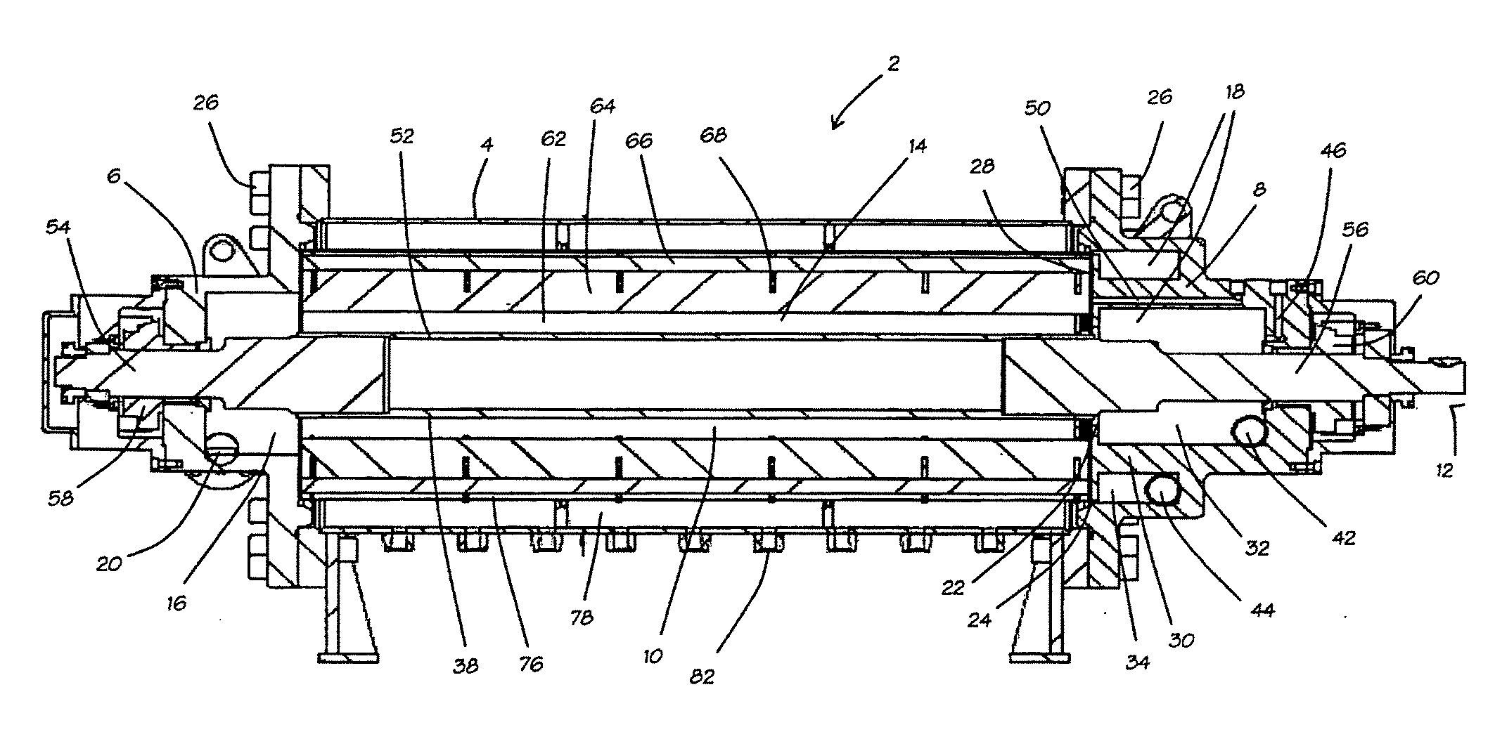
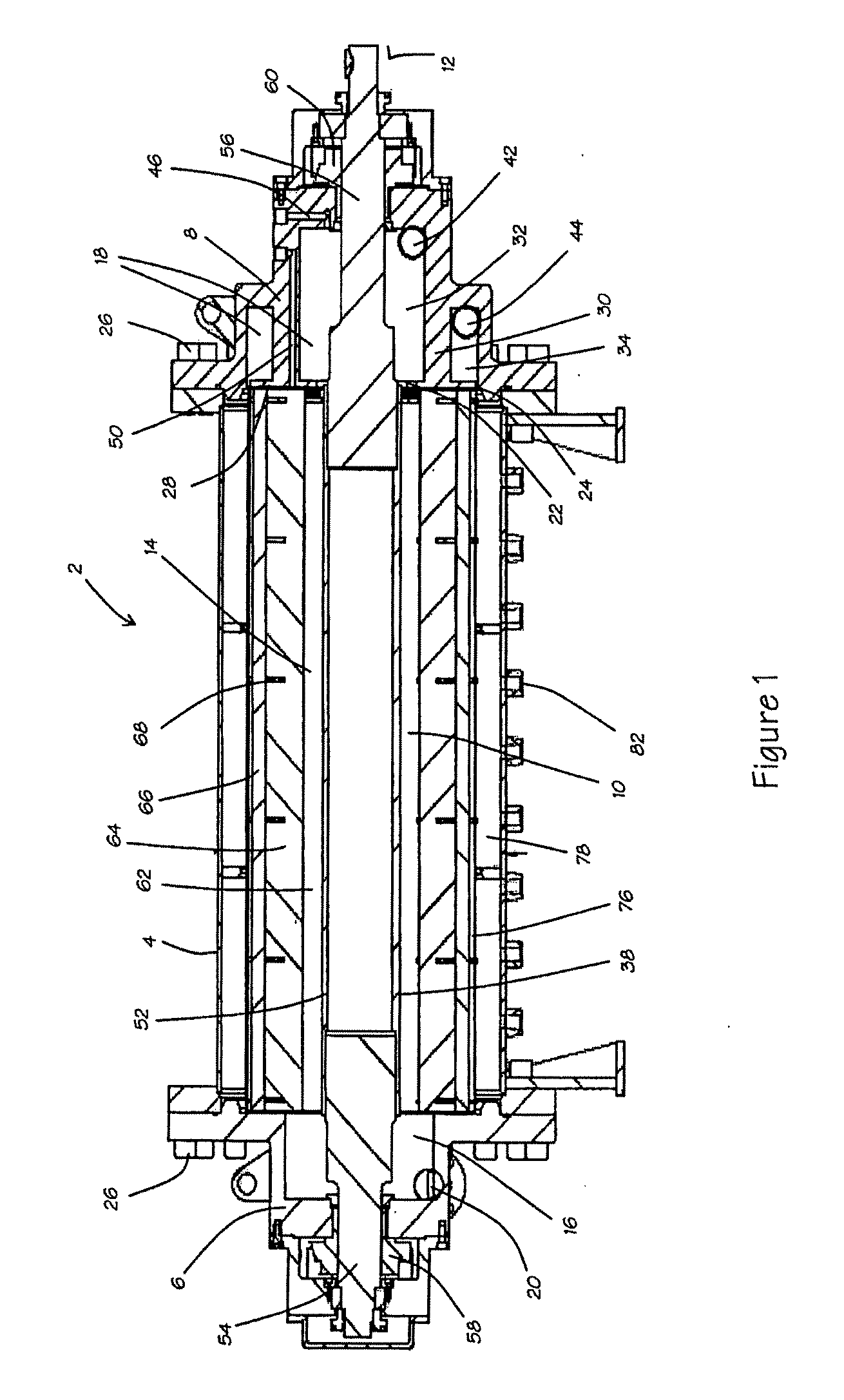
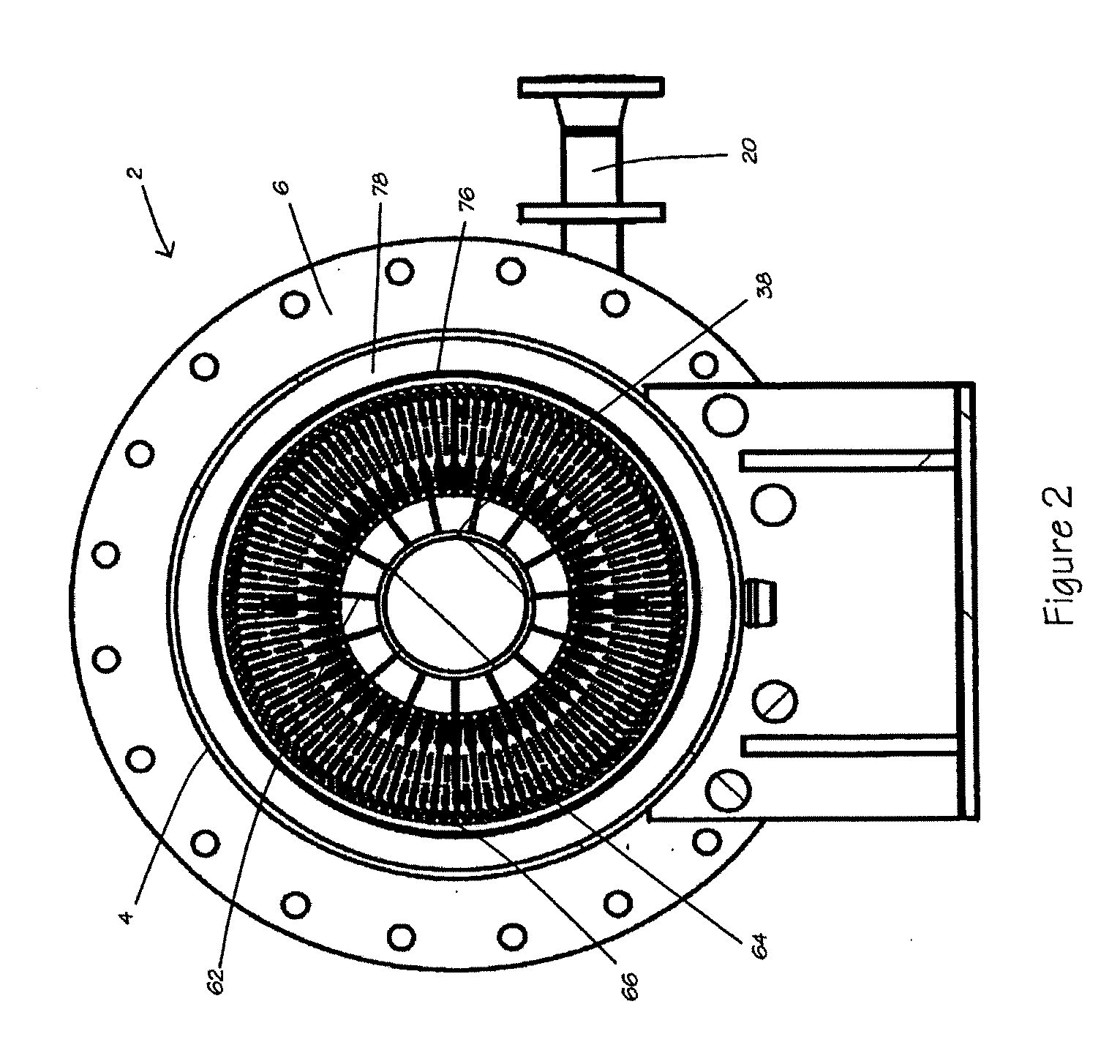
[0043]With reference to FIGS. 1 and 2, the separator comprises a vessel 2, constructed from an outer wall 4 and end caps 6 and 8. The interior of the vessel 2 defines a separation chamber 10 in which a rotor 12 is mounted for rotation.

[0044]The separation chamber 10 is substantially cylindrical and comprises a central region 14 and inlet and outlet end regions 16, 18. A mixture inlet 20 opens into the inlet region 16, and light and heavy phase outlets 22, 24 open into the outlet region 18. The inlet and outlet end regions 16,18 are defined within the respective end caps 6,8 which are attached to the outer wall by bolts 26 passing through respective flanges of the end caps 6, 8 and the outer wall 4. The inlet end region 16 is substantially cylindrical with a diameter less than that of the central region 14. The inlet 20 comprises a cylindrical passage disposed tangentially to the longitudinal axis of the separation chamber 10.

[0045]The outlet end region 18 is also substantially cylin...


PUM

PropertyMeasurementUnit
angleaaaaaaaaaa
distancesaaaaaaaaaa
differential pressureaaaaaaaaaa

Abstract

A separator device comprises a cylindrical separation chamber within which a motor-driven rotor is situated. The rotor has vanes. In operation, an inflowing mixture enters through an inlet and is subjected to centrifugal force imposed by the rotation of the rotor. A lighter liquid fraction leaves through an annular outlet, and a heavier liquid fraction leaves through an annular outlet. Solids pass through a screen to a region where rotational flow is reduced or absent. The solids in the region are fluidized by liquid passing through the screen, and are extracted from outlets.Control means is provided to control operation of the device in response to changes in the incoming mixture.

Description

BACKGROUND OF THE INVENTION[0001]This invention relates to a separation device, and is particularly, although not exclusively, concerned with a separation device for separating components of an incoming mixture comprising liquid phases of different densities, and a solid component.[0002]The separation of components and phases of a fluid mixture is important in many industrial processes. In the context of this specification, the term “phase” is used not simply to refer to different states (solid, liquid or gas) of a material, but more generally to embrace different materials that are in the same state as each other (e.g. two immiscible liquid components of different densities).[0003]The separation of immiscible liquids is particularly challenging, especially when their densities differ only slightly. If solids are present in the mixture, the solids can provide nucleation sites in one or other of the liquid components, so promoting the formation of stable emulsions. If such stable emu...

Claims


Application Information

Patent Timeline
Patent Type & Authority Applications(United States)
IPC IPC(8): B04B5/10B01D17/038
CPCB01D17/0217B01D21/10B04B5/12B01D21/262B04B2005/125B01D21/26
Inventor COLLIER, KEVIN E.PARKINSON, DAVID J.
Owner SPECIALIST PROCESS TECH
Why Eureka
Try Eureka