
Plate for the treatment of bone fractures

a plate and bone fracture technology, applied in the field of plate for the treatment of bone fractures, can solve the problems of plate fatigue failure, plate increase the risk of mal-union or non-union, plate reduce the strength of the plate, etc., and achieve the effect of a larger cross-section

Active Publication Date: 2011-01-06
ZIMMER GMBH
View PDF99 Cites 40 Cited by
  • Summary
  • Abstract
  • Description
  • Claims
  • Application Information

AI Technical Summary

Benefits of technology

[0008]Conventional plates used in osteosynthesis typically have a cross-section formed by two concentric radii. In contrast to this cross-section, the plate of the present disclosure has an increased strength and a lower stiffness for a given thickness and width as compared to a conventional circle segmented design. The increased strength has the advantage that it reduces the probability of fatigue failure of the plate, and the reduced stiffness advantageously reduces the risk of mal-union or non-union due to the stress-shielding effect. The fact that the second surface is adapted and suited to facing the surface of the bone at the fracture site enables a more secure fixation of the plate at the fracture site. Moreover, the manufacturing process is improved, as the conventional cross-section having two concentric radii is more costly and work intensive.
[0023]In a further aspect of the present disclosure at least one hole for a bone screw is provided in the plate extending between the first surface and the second surface, with the bone screw being adapted for fixing the plate to the bone. This leads to an improved attachment means for the bone plate to the bone, and depending on the size of the fracture, and / or the number of fractured bone segments aids the healing process advantageously.

Problems solved by technology

However, a stiff plate increases the risk of mal-union or non-union due to the stress-shielding effect.
However, this reduces the strength of the plate and in some cases can lead to fatigue failure of the plate.
Moreover, the manufacturing process is improved, as the conventional cross-section having two concentric radii is more costly and work intensive.

Method used


Image

  • Plate for the treatment of bone fractures
  • Plate for the treatment of bone fractures
  • Plate for the treatment of bone fractures

Examples


Embodiment Construction

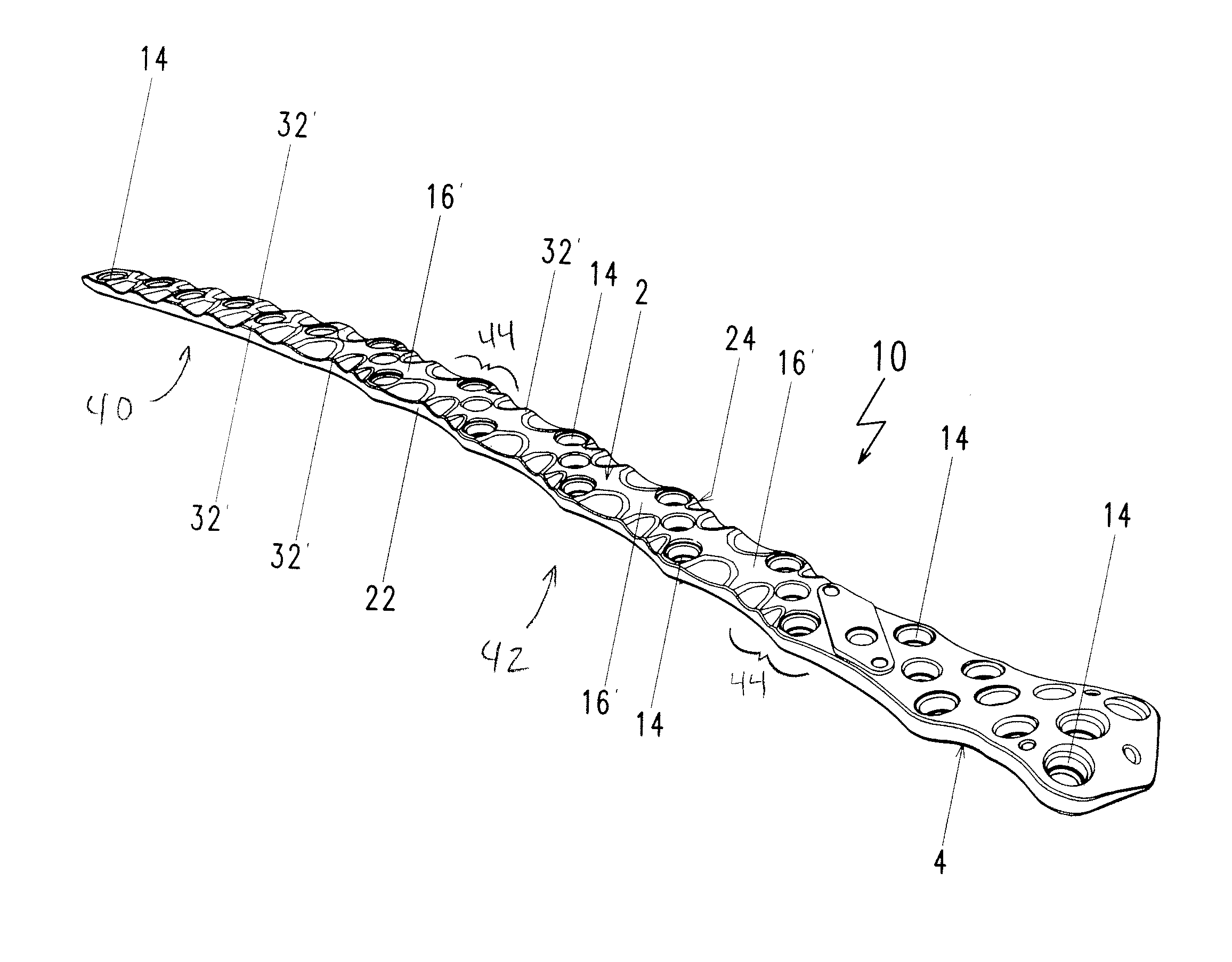
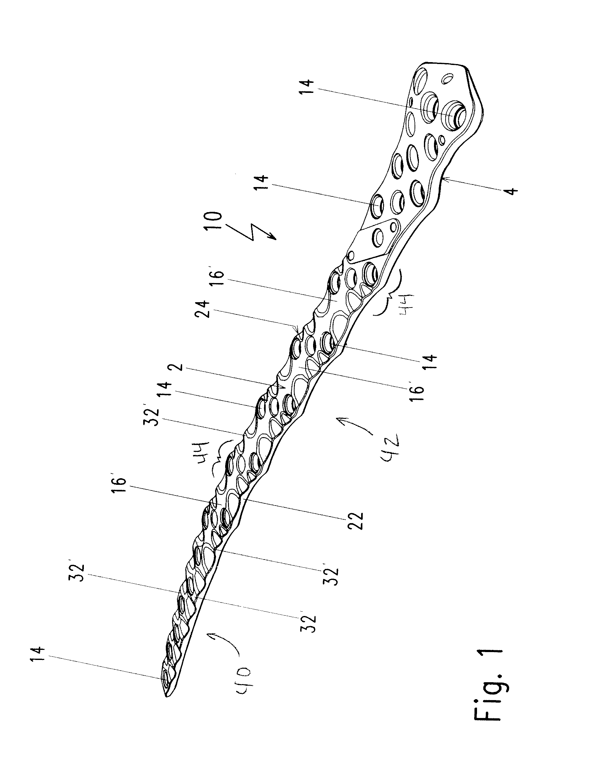
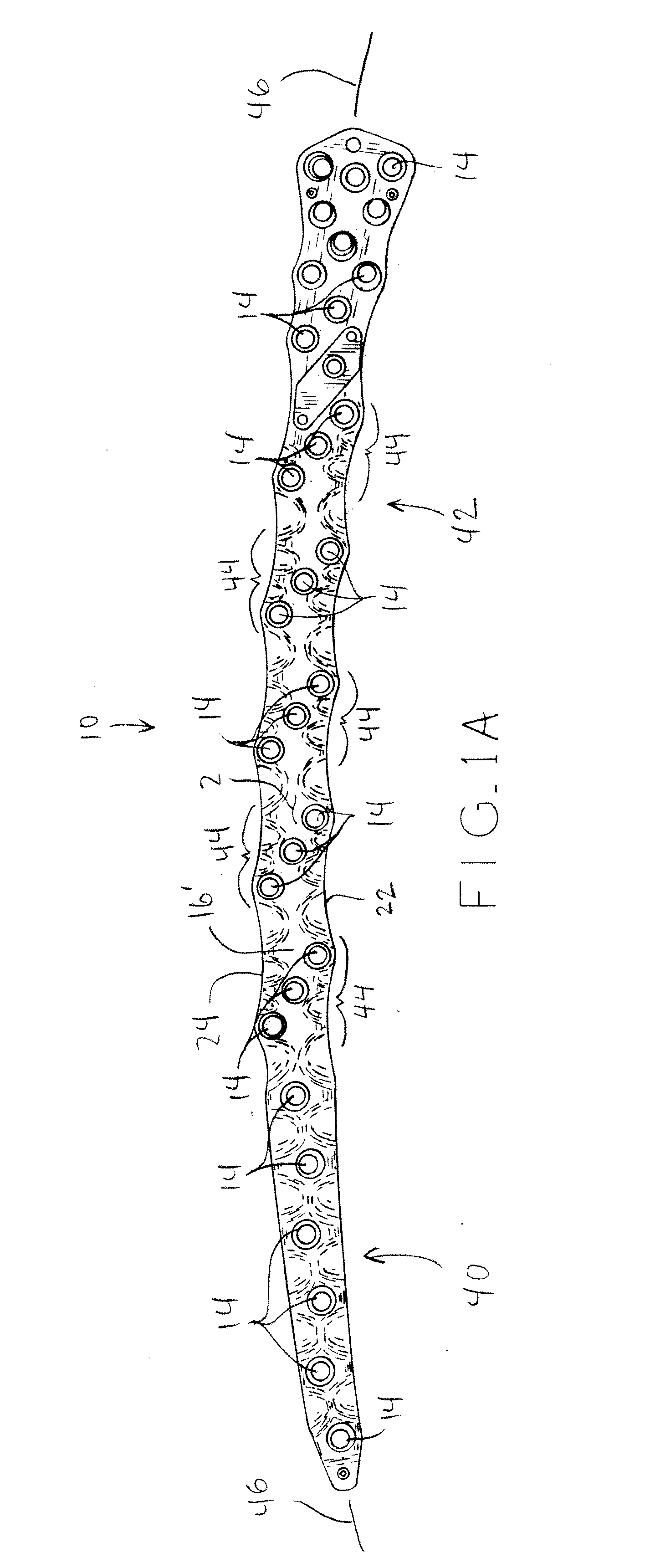
[0037]FIG. 1 shows a plate, such as distal femur plate 10 to be attached to fractured thigh bone surface 6 (FIG. 2). First or top surface 2 has a plurality of holes 14 and a plurality of portions 16′ which—when seen in cross section as explained below—define generally linearly shaped or planar portions 16′ and whose respective width varies along the length of plate 10 in accordance with the size and the shape of the bone. Moreover, a plurality of portions 32′ are provided which—when seen in cross section as explained below—define different non-linearly shaped or non-planar portions 32′. Holes 14 shown in top surface 2 of plate 10 extend through to second surface 4 which is also known as the bone facing surface 4 or a bottom surface 4. Holes 14 are ideally used in connection with bone screws, which are adapted to fix plate 10 to bone surface 6.

[0038]In the following the same reference numerals are used for like features, such as features that are either similar in design or fulfill t...


PUM


Abstract

A plate is provided for the treatment of bone fractures, the plate having a first surface and a second surface, the second surface being opposed to the first surface and being adapted to face a bone surface. At least one of the first and second surfaces defines at least one generally linearly shaped portion of a boundary of at least one cross section of the plate.

Description

CROSS-REFERENCE TO RELATED APPLICATIONS[0001]This application claims priority from European Patent Application No. EP09008867.5, filed Jul. 7, 2009, the disclosure of which is hereby expressly incorporated by reference herein in its entirety.BACKGROUND[0002]1. Field of the Disclosure[0003]The present disclosure relates to a plate for the treatment of bone fractures.[0004]2. Description of the Related Art[0005]To aid the treatment and healing process of fractured bones, it is known to use plates, screws, pins and wire cerclages as internal fixation means. For complicated fractures the bone and the bone fragments have to be fixated securely by use of plates. However, a stiff plate increases the risk of mal-union or non-union due to the stress-shielding effect.[0006]To reduce the risk of mal-union or non-union due to the stress-shielding effect, one has to reduce the stiffness of the plate. However, this reduces the strength of the plate and in some cases can lead to fatigue failure of...

Claims


Application Information

Patent Timeline
IPC IPC(8): A61B17/80
CPCA61B17/8061A61B17/80A61B17/82
Inventor VELIKOV, JORDAN
Owner ZIMMER GMBH
Learn More