
Method for operating a hybrid vehicle and hybrid vehicle

a hybrid vehicle and hybrid technology, applied in the direction of propulsion parts, propulsion using engine-driven generators, process and machine control, etc., can solve the problems of reducing the energy recovery during regenerative braking, lower engine losses, and higher losses, so as to maximize the energy recovery of electric machines, reduce the amount of recovered energy, and increase the transmission ratio

Active Publication Date: 2011-01-06
VOLVO LASTVAGNAR AB
View PDF14 Cites 5 Cited by
  • Summary
  • Abstract
  • Description
  • Claims
  • Application Information

AI Technical Summary

Benefits of technology

[0003]It is desirable to provide a method for operating a hybrid vehicle which allows for improving the recovery of kinetic energy. It is also desirable to provide a hybrid vehicle providing an efficient energy recovery.
[0023]Preferably, a clutch can be provided between the first drive unit and the drive train. When a request for shut-down is emitted, the first drive unit can be shut off and decoupled from the drive train early thus saving energy by saving fuel.

Problems solved by technology

A high gear results in lower losses of the engine while driving and a low gear results in higher losses.
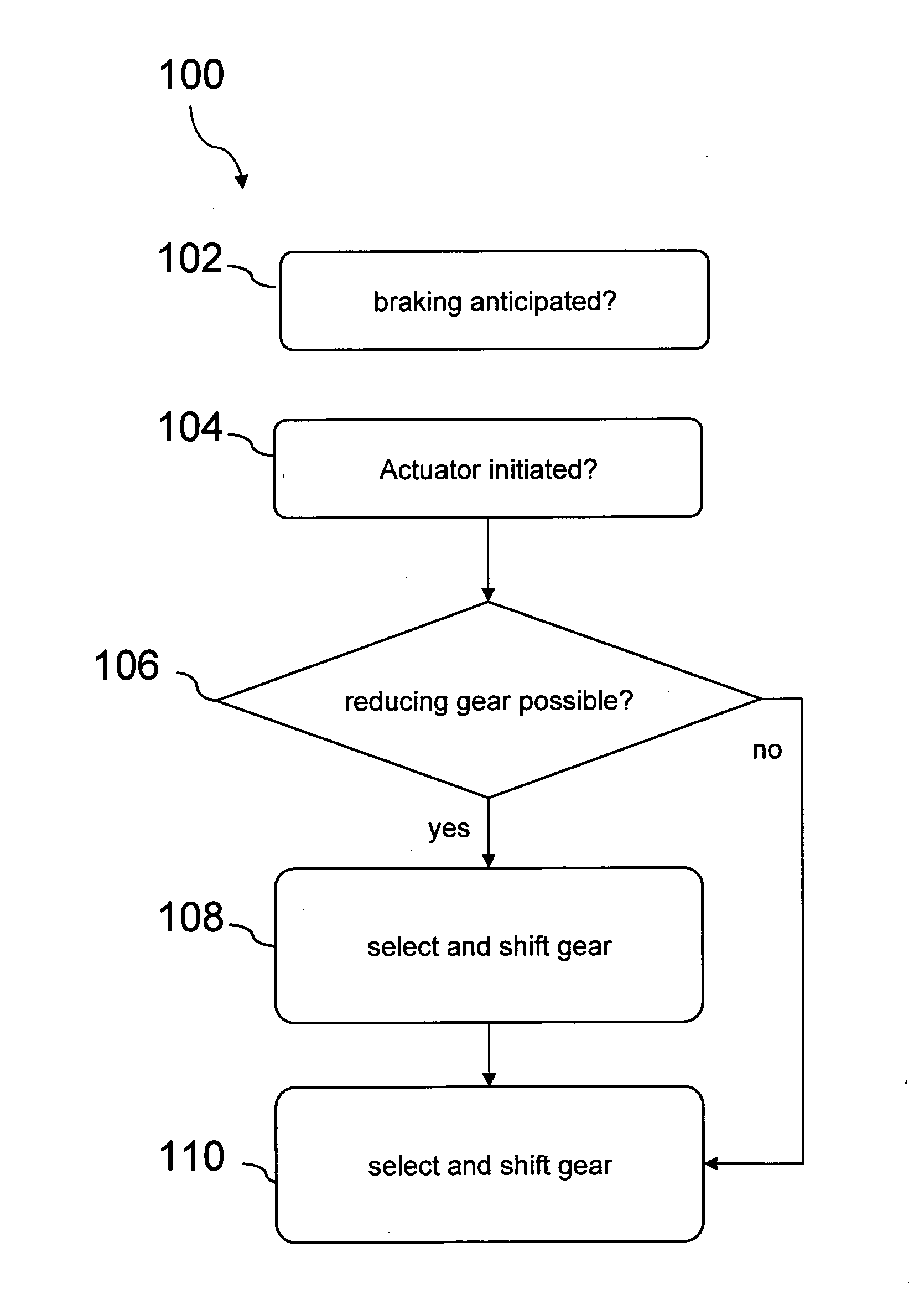
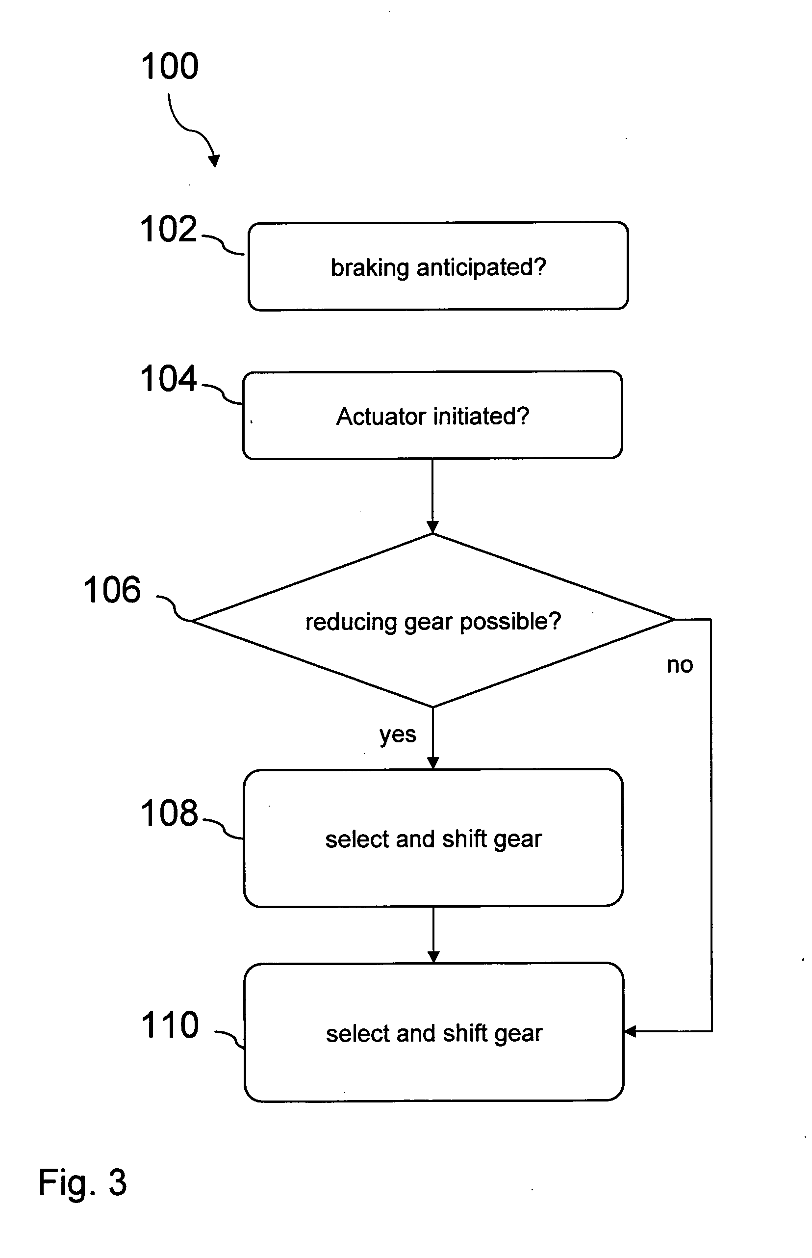
By checking if the gear of the transmission unit can be reduced in favour of the rotational speed of the electric machine it can be avoided to start braking from a high gear which is favourable for reducing losses of the engine but reduces the energy recovery during regenerative braking when the electric machine is operated as generator.
However, if it is realized that increasing the transmission ratio is not favourable for the energy recovery of the second drive unit, a gearshift is omitted.
For instance, if the lowest gear is already set, a change to a lower gear cannot be performed, or if the energy storage is full or nearly full it might not be desired to recover energy.
For instance, if an electric machine is used as a second drive unit, no energy at all can be recovered by the electric machine during the time needed for a gearshift.

Method used


Image

  • Method for operating a hybrid vehicle and hybrid vehicle
  • Method for operating a hybrid vehicle and hybrid vehicle
  • Method for operating a hybrid vehicle and hybrid vehicle

Examples


Embodiment Construction

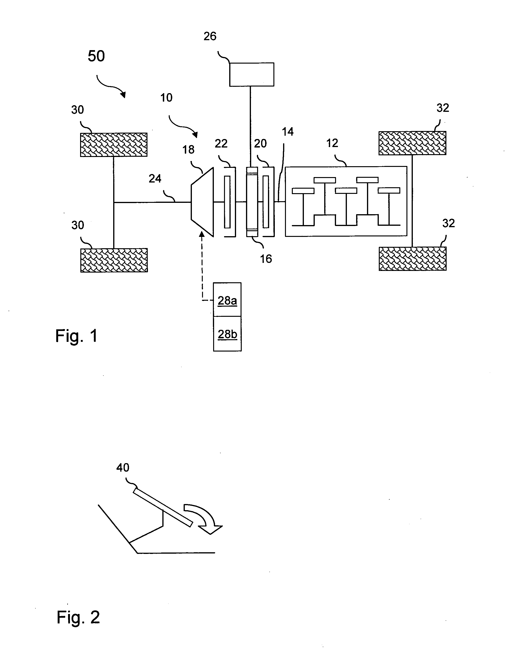
[0032]FIG. 1 illustrates a schematic sketch of a preferred hybrid vehicle 50 according to the invention. The hybrid vehicle 50 comprises a drive train 10 with a first drive unit 12, preferably a combustion engine, and a second drive unit 16, preferably an electric machine, arranged on an output shaft 14 of the first drive unit 12. A transmission unit 18 can be coupled to the first and / or second drive unit 12, 16. Driveable wheels 30 are connected to the drive axle 24. Further wheels 32 of the hybrid vehicle can be non-driveable or driveable (four-wheel drive).

[0033]A first clutch 20 is arranged between the first and the second drive units 12, 16 and an optional second clutch 22 is arranged between the second drive unit 16 and the transmission unit 18. The transmission unit 18 can be an automated manual transmission or an automatic transmission controlled by a transmission control unit (not shown). If the first clutch 20 is open and the second clutch 22 closed, the second drive unit ...


PUM


Abstract

A hybrid vehicle and a method for operating a hybrid vehicle are provided, the vehicle including at least a first drive unit and a second drive unit coupled to the first drive unit, wherein the second driving unit recovers kinetic energy during braking the hybrid vehicle, a transmission unit which can be coupled to the first and / or second drive unit and a drive axle. It is proposed to change the transmission ratio of the transmission unit depending on a desired amount of energy recovered by the second drive unit during regenerative braking or a predetermined time period before the anticipated start of regenerative braking.

Description

BACKGROUND AND SUMMARY[0001]The invention relates to a method for operating a hybrid vehicle and a hybrid vehicle according to the independent claims.[0002]Hybrid vehicles with a multitude of drive units, e.g. a combustion engine and an electric machine coupled to the combustion engine are known in the art. When a hybrid vehicle decelerates, kinetic energy can be recovered by operating the electric machine as a generator and storing the recovered energy in a storage device, e.g. a battery, a super capacitor or the like. The electric machine can be used for a stop-start operation mode of the vehicle. U.S. Pat. No. 7,131,510 B2 discloses a stop-start operation mode of a hybrid vehicle. During a stop stage, the internal combustion engine is disconnected from the electric machine as well as from the transmission system and switched off. In a subsequent start stage, the engine is automatically restarted by the electric machine, which is now operated as a motor, and reconnected to the tra...

Claims


Application Information

Patent Timeline
Patent Type & Authority Applications(United States)
IPC IPC(8): G06F19/00B60L50/16B60W10/10B60W10/18B60W30/18
CPCB60K6/48Y02T10/70B60L7/26B60L11/14B60L2240/80B60L2250/18B60L2250/24B60L2250/26B60W10/06B60W10/08B60W10/10B60W10/11B60W10/196B60W20/00B60W30/18127B60W30/18136B60W2540/12Y02T10/56Y02T10/6221Y02T10/6286Y02T10/7077Y02T10/92B60L7/18B60K2006/268B60L50/16Y02T10/40Y02T10/60Y02T10/62Y02T10/7072Y02T10/84B60W20/13
Inventor RUTQUIST, PEREHRLICH, LISA
Owner VOLVO LASTVAGNAR AB
Learn More