Percussion tool

a percussion tool and buffer technology, applied in the field of percussion tools, can solve the problems of internal operator forgetting to replace the buffer, and wear and tear of successive buffers, so as to reduce the risk of damage to the percussion tool

Active Publication Date: 2011-01-13
ATLAS COPCO AIRPOWER NV
View PDF23 Cites 6 Cited by
  • Summary
  • Abstract
  • Description
  • Claims
  • Application Information

AI Technical Summary

Benefits of technology

[0008]The object of the present invention according to the patent claims is to obtain a pneumatic percussion tool mainly for breaking up concrete and other demolition jobs for which the running stops automatically when the buffer reaches a predetermined degree of wear and when the operator is not pressing the tool against the work site. Another purpose is to achieve a visible indication to the operator that the pre-determined degree of wear has been reached. The main benefit of the invention is to lessen the risk of damage to the percussion tool from forgetting to change the buffer.

Problems solved by technology

The buffer wears down successively during use of the percussion tool and has to be replaced when it reaches a certain degree of wear.
There is a risk that the operator will forget to replace the buffer and thereby risks causing internal damage to the percussion tool.
Under this type of normal use of the percussion tool, only slight wear will occur on the buffer.
By far the greatest wear on the buffer occurs in cases when the operator leaves the percussion tool running, i.e., leaves the pressurised air to continue acting on the percussion tool, without the insert tool being in contact with the work site (in English, “backhammering”).
The effect of the above-described pattern of use means that the buffer of the percussion tool is successively worn down and has to be replaced.
The wear can have a rapid course, since the percussion tool will strike continually for as long as pressurised air is working on it.
If the operator forgets to replace the buffer, this will result in costly damage to internal parts of the percussion tool and halting of operations.
With known percussion tools of this type it is difficult for the operator to know when it is time to replace the buffer.
It is also quite possible for the operator to make the mistake of using the percussion tool in the above-described manner, even though the buffer is fully worn down or has reached an unacceptable degree of wear.
However, the solution is not applicable to pneumatic percussion tools of the above type with buffer, since the English percussion tool is electrically operated and lacks a buffer.

Method used


Image

  • Percussion tool
  • Percussion tool
  • Percussion tool

Examples


Embodiment Construction

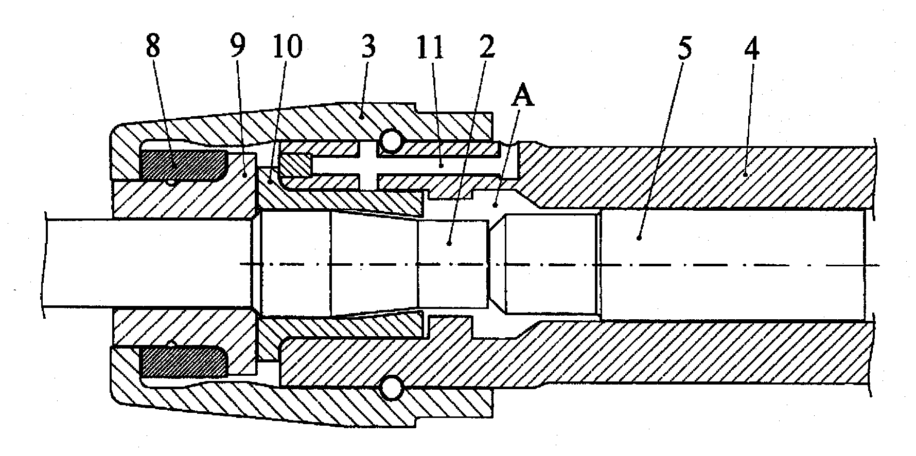
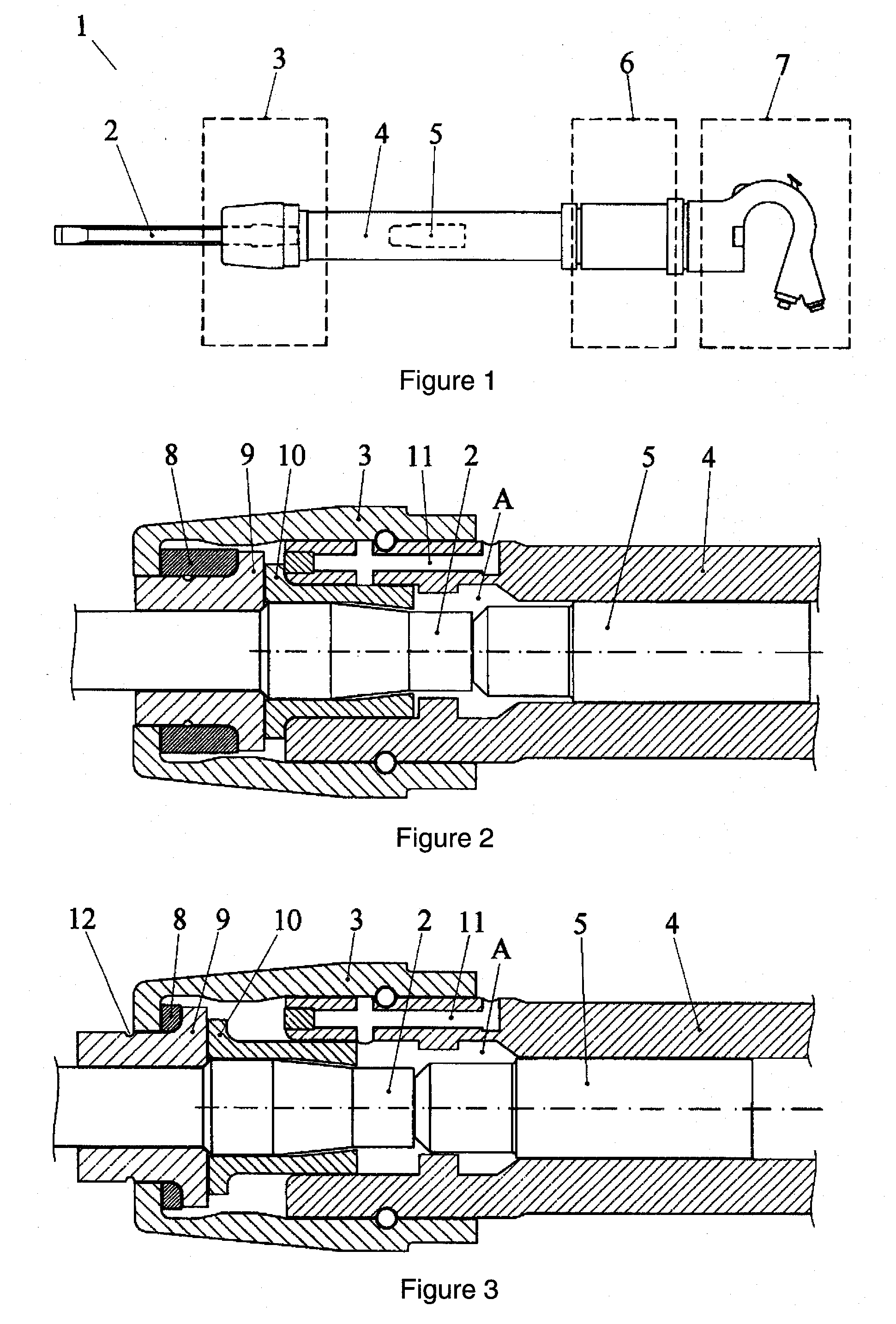
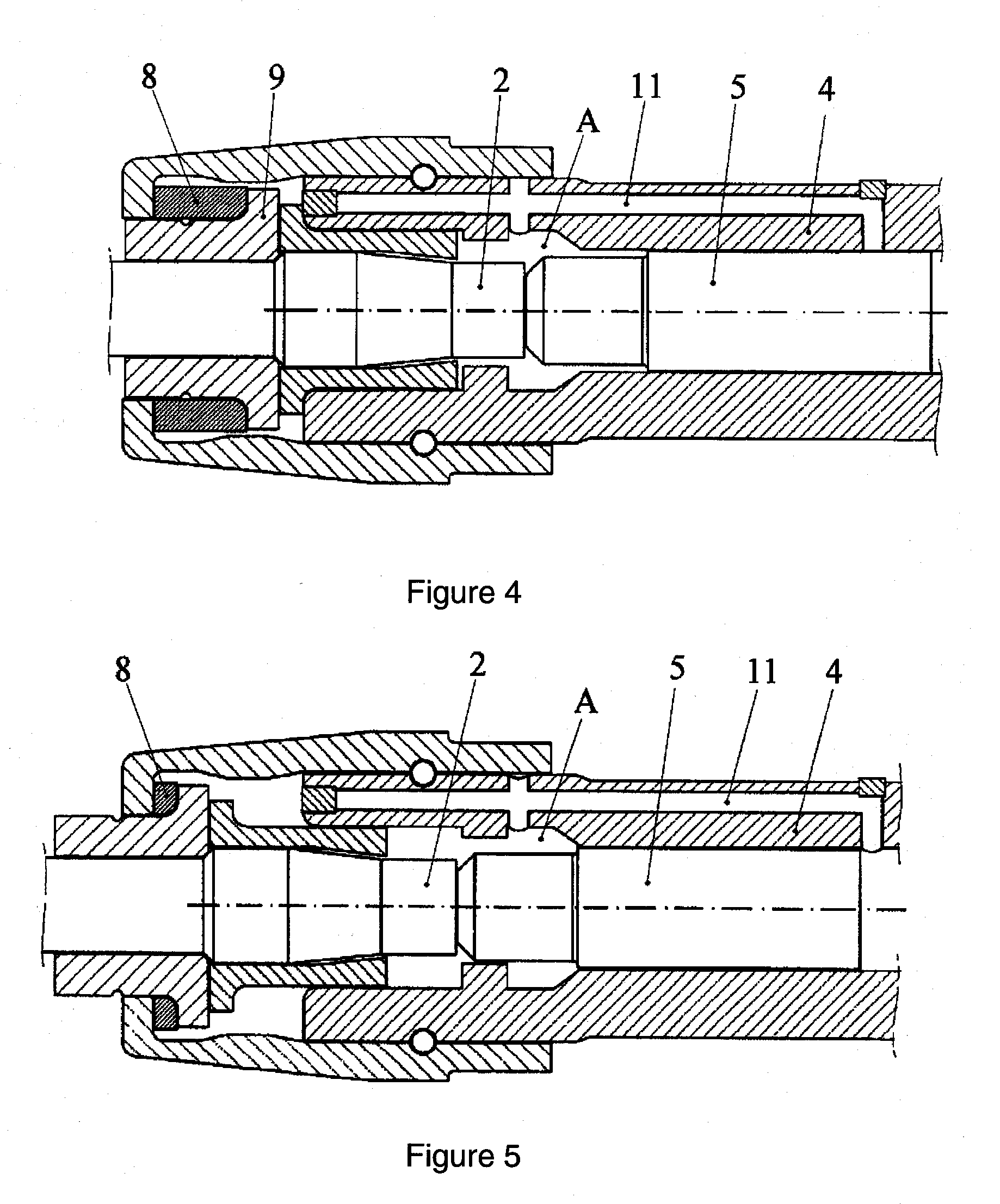
[0014]FIG. 1 shows a pneumatic percussion tool 1, comprising an insert tool 2, a tool holder 3, a percussion cylinder 4, a piston 5, a valve unit 6 and a handle part 7. The upper end of the percussion cylinder 4 is connected to the valve unit 6 and its lower end to the tool holder 3 via a locking spring. It is also possible to use a threaded connection instead of a locking spring. The handle part 7 can be variously configured and comprises a handle, air controls, and connections for compressed air supply. When the operator works the air controls, pressurised air goes to the valve unit 6, which automatically and alternatingly applies pressure to the upper and lower end of the percussion cylinder 4. The alternating pressure makes the piston 5 move in reciprocation inside the percussion cylinder 4. This motion occurs repetitively for as long as pressurised air goes to the valve unit. The frequency is often in the range of 10-50 Hz, but even higher frequencies are conceivable. The pisto...


PUM

PropertyMeasurementUnit
striking frequencyaaaaaaaaaa
frequenciesaaaaaaaaaa
pressureaaaaaaaaaa

Abstract

A pneumatic percussion tool (1) for demolition and/or breaking work in for example concrete and connectable to an insert tool (2). The percussion tool has a percussion cylinder (4), a piston (5), arranged to travel in the bore of the cylinder (4), a buffer (8), and a valve unit (6), designed to act on the piston (5) during operation and produce a repetitive reciprocating travel in the bore of the cylinder (4) by alternately applying pressure to the upper or lower end of the cylinder (4) while the insert tool (2) is subject to influence by the stroke of the piston (5) when this is at its dead centre at the lower end of the cylinder (4). The percussion tool comprises a means (11) of preventing the piston's reciprocating motion when the buffer (8) reaches a predetermined degree of wear and the tool is not pressed against any object being worked.

Description

TECHNICAL FIELD[0001]The invention concerns a percussion tool driven by pressurised air for demolition and / or breaking work, for example in concrete, according to the preamble of patent claim 1.BACKGROUND[0002]Percussion tools like the above can be used mainly for breaking up concrete and other demolition jobs, but also for example to remove rivets, whence the common English term “rivet buster” or rivet hammer.[0003]The percussion tool has an interchangeable insert tool and can be adapted to a number of different application fields by replacing the tool. The percussion tool comprises a buffer to absorb the impact energy that is not transmitted to the work site. The buffer wears down successively during use of the percussion tool and has to be replaced when it reaches a certain degree of wear. There is a risk that the operator will forget to replace the buffer and thereby risks causing internal damage to the percussion tool.[0004]When working with percussion tools of this type, the o...

Claims


Application Information

Patent Timeline
Patent Type & Authority Applications(United States)
IPC IPC(8): B25D17/24B25D9/16B25D17/00
CPCB25D11/005B25D17/06B25D17/24B25D2250/231B25D2250/035B25D2250/101B25D2222/57
Inventor OSTENSSON, OLOF
Owner ATLAS COPCO AIRPOWER NV
Why Eureka
Try Eureka