Apparatus for forming pattern using laser

a technology of pattern and laser, which is applied in the direction of optical elements, instruments, manufacturing tools, etc., can solve the problems of not being able to guarantee the uniformity of light guide, and the deviation of carbon dioxide (cosub>2/sub>) laser

Inactive Publication Date: 2011-01-13
HB TECH CO LTD
View PDF6 Cites 2 Cited by
  • Summary
  • Abstract
  • Description
  • Claims
  • Application Information

AI Technical Summary

Benefits of technology

[0010]An aspect of exemplary embodiments of the present invention is to address at least the problems and / or disadvantages and to provide at least the advantages described below. Accordingly, an aspect of exemplary embodiments of the present invention is to provide an apparatus for forming a pattern using a laser, for equalizing an output of waving laser and securing the uniformity of light guide patterns manufactured through this.

Problems solved by technology

However, the Carbon Dioxide (CO2) laser has a deviation because of its inconstant output.
This leads to a problem of not being capable of guaranteeing the uniformity of the light guide patterns 15 formed in the light guide panel 11.
In this case, there is a problem of the occurrence of an exterior warp phenomenon in which it is seen that the light guide patterns 15 formed in the light guide panel 11 are seemingly curved or warped along their edges due to several main causes.

Method used


Image

  • Apparatus for forming pattern using laser
  • Apparatus for forming pattern using laser
  • Apparatus for forming pattern using laser

Examples


Embodiment Construction

[0027]Exemplary embodiments of the present invention will now be described in detail with reference to the annexed drawings. In the following description, a detailed description of known functions and configurations incorporated herein has been omitted for conciseness.

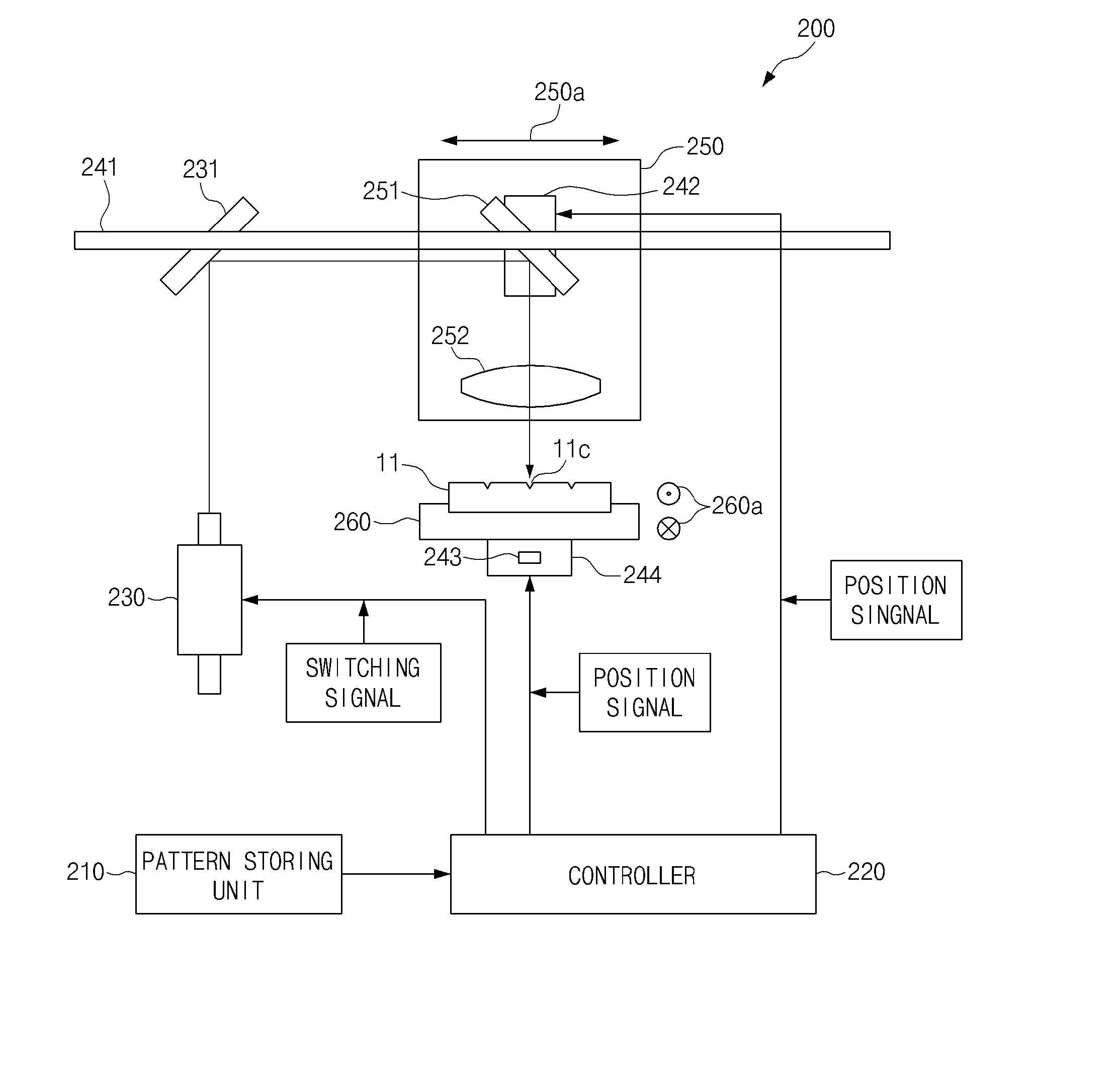
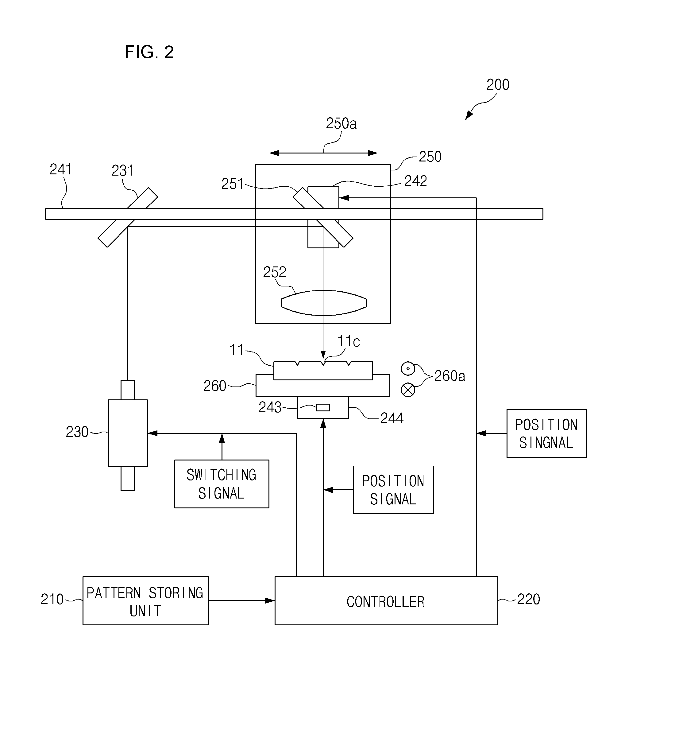
[0028]FIG. 2 is a diagram illustrating the whole construction of an apparatus for forming a pattern using a laser according to an exemplary embodiment of the present invention. The apparatus 200 includes a pattern storing unit 210, a controller 220, a laser oscillating unit 230, an X driver (i.e., a first driver) 242, a Y driver (i.e., a second driver) 244, a header unit 250, and a stage 260.

[0029]Referring to FIG. 2, the pattern storing unit 210 stores data on light guide patterns 11c of a discontinuous straight line shape to be formed in a light guide panel 11. In detail, the light guide patterns data can include position signal (i.e., X and Y coordinates) and length information on each light guide pattern 11c.

[0030...


PUM

PropertyMeasurementUnit
lengthaaaaaaaaaa
lengthaaaaaaaaaa
transparentaaaaaaaaaa

Abstract

An apparatus for forming a pattern using a laser is provided. The apparatus includes a pattern storing unit, a controller, a laser oscillating unit, an X-Y driver, a header unit, and a stage. The pattern storing unit stores data on light guide patterns of a discontinuous straight line shape. The controller transmits position signal of the light guide patterns to the X-Y driver and simultaneously, transmits a switching signal to the laser oscillating unit. The laser oscillating unit outputs a laser beam synchronized with a movement of the header unit. The X-Y driver moves the header unit and the stage. The header unit moves along a first guide rail. The stage moves along a fixed second guide rail in the front and rear direction of the light guide panel.

Description

CROSS REFERENCE[0001]This application claims foreign priority under Paris Convention and 35 U.S.C. §119 to Korean Patent Application No. 10-2009-0062799, filed Jul. 10, 2009 with the Korean Intellectual Property Office.BACKGROUND OF THE INVENTION[0002]1. Technical Field[0003]The present invention relates to manufacturing a pattern of a light guide panel of a surface light source device used in a liquid crystal display device, a lighting signboard, a cellular phone, a telephone, a Personal Digital Assistant (PDA), a keyboard, an electronic calculator, etc. More particularly, the present invention relates to an apparatus for forming a pattern using a laser, for equalizing an output of waving laser and securing the uniformity of light guide patterns, by splitting and forming the light guide patterns through many times.[0004]2. Description of the Related Art[0005]Commonly, a light guide panel, which is a plate for providing a path for uniformly scattering and diffusing light scanned fro...

Claims


Application Information

Patent Timeline
Patent Type & Authority Applications(United States)
IPC IPC(8): B23K26/08
CPCB41J2/442G02B6/0065G02B6/0036B41J2/47G02B6/00B23K26/08
Inventor PARK, DEUKILRHEW, CHOONGYOPPARK, DAISOUNGKANG, WONMYEONG
Owner HB TECH CO LTD
Why Eureka
Try Eureka