Apparatus for the Inductive Heating of Oil Sand and Heavy Oil Deposits by way of Current-Carrying Conductors

a technology of inductive heating and conductors, which is applied in the direction of induction heating, insulation, and wellbore/well accessories, etc., can solve the problems of high production costs, high production costs and expensive high-voltage ceramics, and inability to control the reactive power of the reactive power, so as to reduce or avoid the addition of ohmic losses , the effect of increasing the resistan

Inactive Publication Date: 2011-01-13
SIEMENS AG
View PDF6 Cites 29 Cited by
  • Summary
  • Abstract
  • Description
  • Claims
  • Application Information

AI Technical Summary

Benefits of technology

[0017]In particular, the developments and specific details of the invention mentioned above pose the following advantages:
[0020]the use of HF litz wires reduces or avoids the additional ohmic losses caused by the skin effect.
[0022]In the invention, the weaving or transposing of the individual conductors within the resonance length avoids additional ohmic losses caused by the ‘proximity effect’. It also reduces the requirements of the electric strength of the insulation of the dielectric through more homogeneous displacement current densities. The arrangement of a plurality of conductor sub-groups about the common centre makes it possible to use stranded wires (instead of woven or transposed wires without having to forego the reduction in additional ohmic losses caused by the proximity effect) and to simultaneously achieve simplified production.
[0023]When laying the inductor, as intended, in the reservoir of oil sand deposits, tensile stresses of several tens of tonnes are to be expected and could overburden the compensated conductor, weakened by interruptions, in such a way that, for example, the electric strength of the dielectric could be reduced. Mechanical reinforcement is thus desirable.
[0024]If the inductor is configured with a small conductor cross-section, in particular a cross-section made of copper, active cooling of the apparatus according to the invention may be necessary, open spaces or gaps advantageously being provided in the apparatus for this purpose. A plastics material pipe holds the bore hole open and protects the inductor during installation and operation. The tensile stress exerted on the inductor when it is drawn in is thus reduced by reducing friction. A liquid in the gap produces a good level of thermal contact relative to the plastics material pipe and relative to the reservoir, which is necessary for passive cooling of the inductor. At an ambient temperature of the reservoir of, for example, 200°C., ohmic losses in the inductor of up to approximately 20 W / m can be dissipated by heat conduction, without the temperature in the inductor exceeding 250°C., which is a critical value for Teflon insulation.
[0025]The flow of coolant in opposite directions inside and outside the conductor makes it possible to obtain a more uniform temperature along the inductor, which may be approximately 1000 m long, than would be possible with flows of coolant in the same direction.

Problems solved by technology

If, for this purpose, the known SAGD method is used exclusively, or inductive heating is used either exclusively or in addition to assist the known SAGD method, there is the problem that the inductive voltage drop along the long length of the inductor of, for example, 1000 m, may lead to very high voltages of up to several hundred kV, the reactive power of which cannot be controlled either in the insulation against the reservoir or the earth, or at the generator.
The former conductor apparatus has different characteristics, such as low flexibility, high production costs and expensive high-voltage ceramics.
The latter conductor apparatus is not suitable for the intended purpose mentioned at the outset.

Method used


Image

  • Apparatus for the Inductive Heating of Oil Sand and Heavy Oil Deposits by way of Current-Carrying Conductors
  • Apparatus for the Inductive Heating of Oil Sand and Heavy Oil Deposits by way of Current-Carrying Conductors
  • Apparatus for the Inductive Heating of Oil Sand and Heavy Oil Deposits by way of Current-Carrying Conductors

Examples


Embodiment Construction

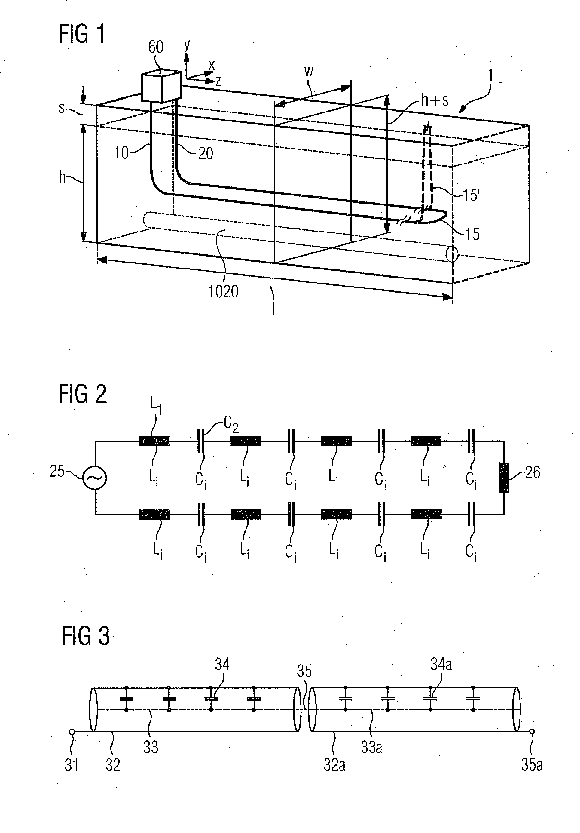
[0041]FIG. 1 shows an oil sand deposit referred to as a reservoir, with reference always being made to a rectangular unit 1 of length 1, width w and height h when making specific observations. The length 1 may, for example, measure up to some 500 m, the width w may measure 60 to 100 m and the height h may measure approximately 20 to 100 m. It should be taken into consideration that, starting from the earth surface E, an ‘overburden’ of thickness s up to 500 m may be provided.

[0042]FIG. 1 shows an apparatus for the inductive heating of the reservoir detail 1. This may be formed by a long, i.e. measuring several hundred meters to 1.5 km, conductor loop 10 to 20 laid in the ground, the outgoing conductor 10 and the return conductor 20 being guided beside one another, i.e. at the same depth, and being interconnected at the end via a member 15 inside or outside the reservoir. At the start, the conductors 10 and 20 are guided down vertically or at a flat angle and may be supplied with ele...


PUM


Abstract

An apparatus for the inductive heating of oil sand and heavy oil deposits by way of current-carrying conductors is provided. The conductors include individual conductor groups, wherein the conductor groups are designed in periodically repeating sections of defined length defining a resonance length, and wherein two or more of the conductor groups are capacitively coupled. In this way, each conductor can be advantageously insulated and may include a single wire.

Description

[0001]This application is the US National Stage of International Application No. PCT / EP2009 / 052183, filed Feb. 25, 2009 and claims the benefit thereof. The International Application claims the benefits of German application No. 10 2008 012 855.4 DE filed Mar. 6, 2008 and German application No. 10 2008 062 326.1 filed Dec. 15, 2008. All of the applications are incorporated by reference herein in their entirety.FIELD OF INVENTION[0002]The invention relates to an apparatus for the inductive heating of oil sand and heavy oil deposits by way of current-carrying conductors.BACKGROUND OF INVENTION[0003]In order to convey heavy oils or bitumen from oil sand or oil shale deposits using pipe systems that are inserted through bore holes, the flowability of said heavy oils or bitumen must be considerably increased. This may be achieved by increasing the temperature of the deposit, referred to hereinafter as a reservoir. If, for this purpose, the known SAGD method is used exclusively, or inducti...

Claims


Application Information

Patent Timeline
Patent Type & Authority Applications(United States)
IPC IPC(8): H05B6/02
CPCE21B36/04E21B43/2401H05B6/108H05B2214/03H05B6/105
Inventor DIEHL, DIRK
Owner SIEMENS AG
Why Eureka
Try Eureka