Insulating housing for motor terminal

a technology for motor terminals and housings, which is applied in the direction of coupling device details, coupling device connections, dynamo-electric components, etc., can solve the problems of large thickness of housing main body, high cost, and inability to meet the needs of a large so as to reduce the number of coil terminals to be protruded therefrom, and reduce the thickness. , the effect of increasing the material yield of plate a material

Active Publication Date: 2011-01-13
MITSUBISHI ELECTRIC CORP
View PDF14 Cites 4 Cited by
  • Summary
  • Abstract
  • Description
  • Claims
  • Application Information

AI Technical Summary

Benefits of technology

[0011]According to the present invention, insert-molding is performed under a condition where the plurality of electricity supply members each having the connector terminal and the coil terminal are disposed spaced in an insulating interval from each other on the same plane. Therefore, placing those components in a superposed manner as in the past is not required, and the insulating housing for a motor terminal can be formed in a thinner shape in a vertical direction, more specifically, in a shape reduced in thickness, thus enabling the entire motor to be produced in a thin shape. Further, due to formation of the electricity supply member in a straight or curved shape, the material yield in forming the electricity supply member from plate a material is increased. Furthermore, when the insulating housing for a motor terminal is assembled to a motor having motor coils of the respective phases wound thereon in series, the maximum number of the coil terminals to be protruded from the insulating housing main body can be six in the case of the motor coils connected in a Y-connection and the maximum number thereof can be three in the case of the motor coils connected in a delta-connection. Thus, the number of coil terminals to be protruded therefrom can be reduced. Consequently, it is possible to reduce the diameter of the insulating housing main body, and in combination with the above points, it is possible to downsize the configuration of the insulating housing main body, and also the number of the coil terminals to be connected is reduced, thus enabling the assembling work to be carried out with simplicity and rapidity.

Problems solved by technology

1) The insulating housing is extremely uneconomical because of low material yield in the production of the electricity supply members.
2) The electricity supply members for the respective phases and the insulating members, each forming a ring, are housed in the housing groove of the housing main body with the electricity supply members and the insulating members placed in an alternately superposed relation, in other words, with an insulating distance vertically put in every space between the electricity supply members, and thus the housing main body becomes large in thickness to increase the size thereof in the assembling direction of the main body to a motor.
3) Placing the electricity supply members and the insulating members in an alternately superposed relation increases the depth of a metal mold, and thus it is difficult to place insert components therein upon a molding process.
4) The number of lead wire connectors of each of the electricity supply members of the respective phases is large. Thus, the number of lead wire connectors projecting from the housing main body is large, and the number of assembling steps to connect the lead wire connectors to motor coils is large to increase difficulty in assembly.

Method used


Image

  • Insulating housing for motor terminal
  • Insulating housing for motor terminal
  • Insulating housing for motor terminal

Examples


first embodiment

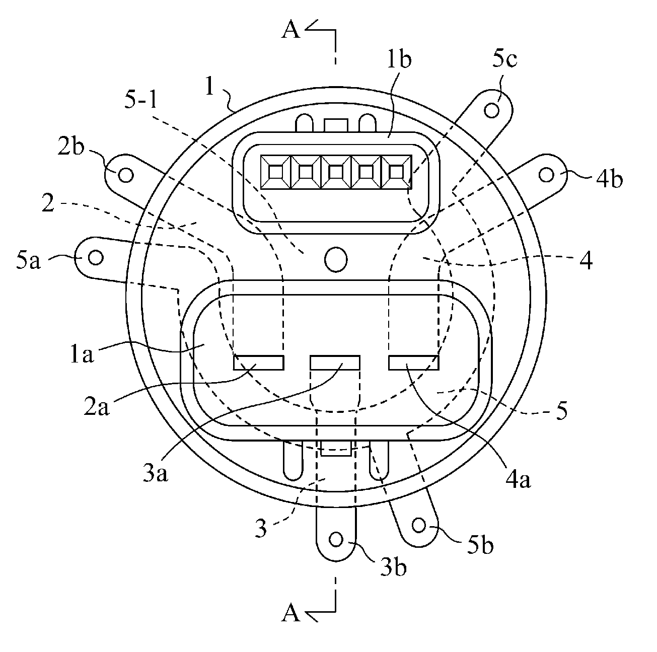
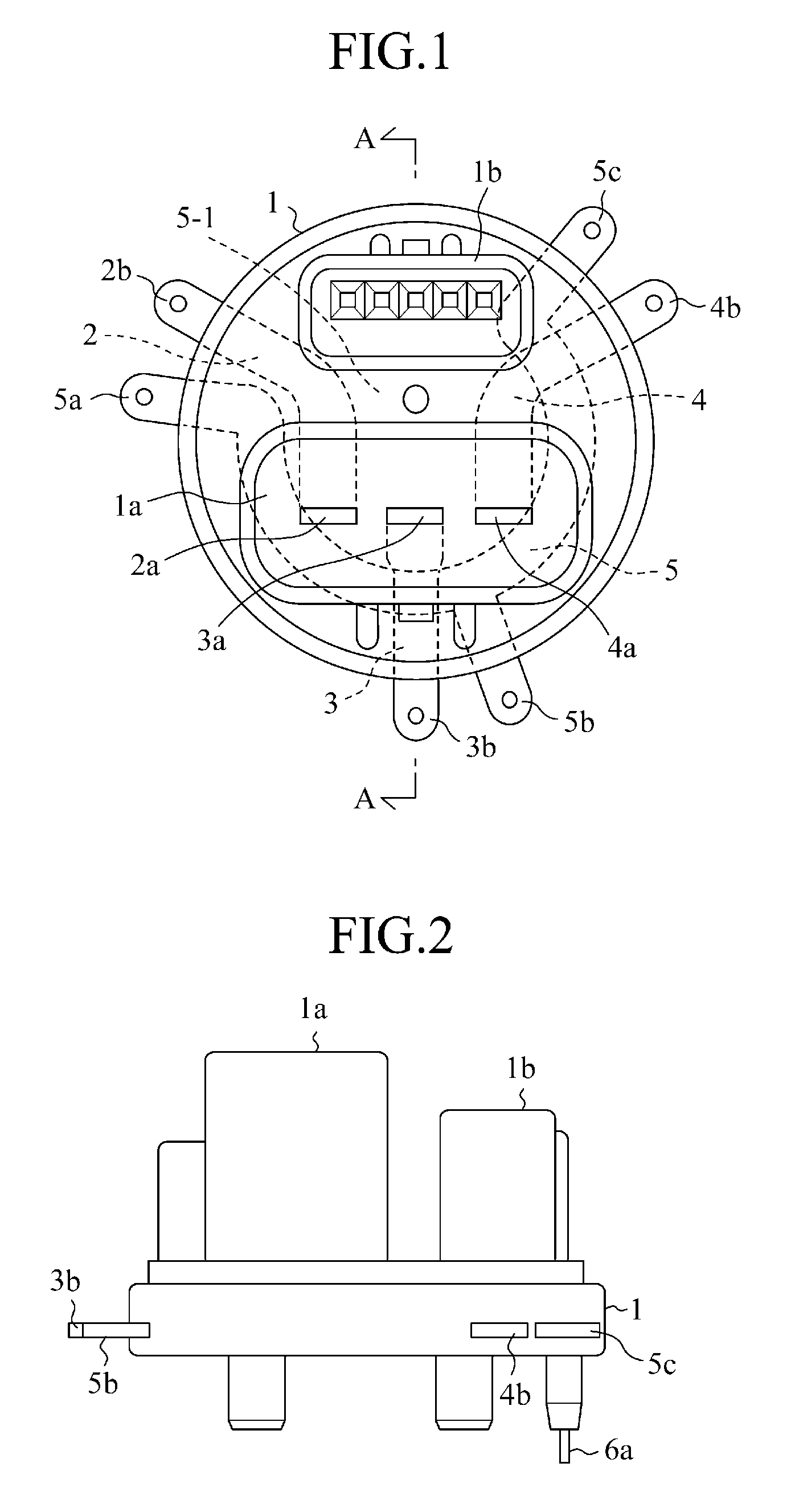
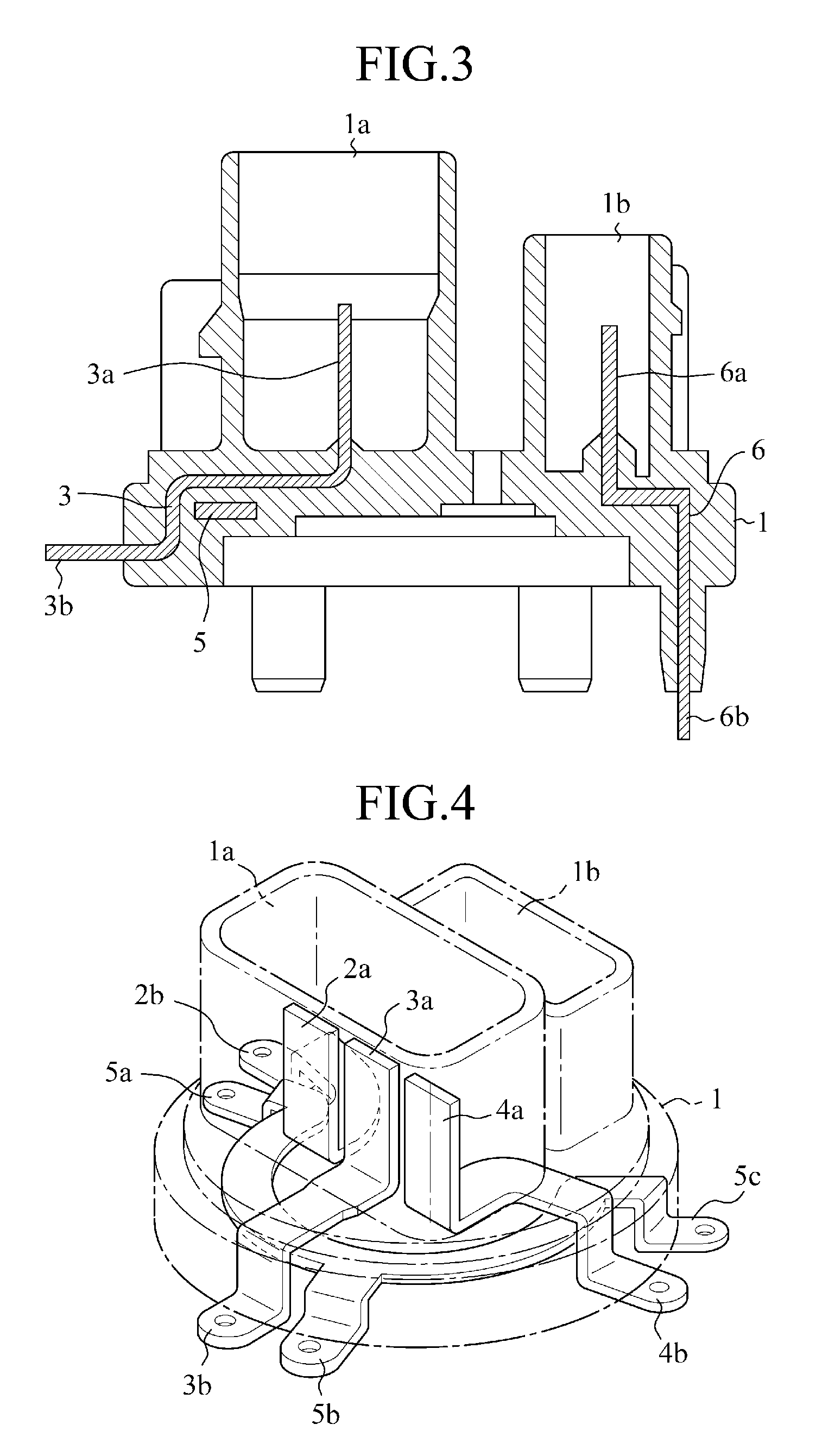
[0021]FIG. 1 is a plan view showing an insulating housing for a motor terminal according to the present invention, FIG. 2 is a plan view thereof, FIG. 3 is a longitudinal sectional view along the line A-A of FIG. 1, FIG. 4 is an perspective view showing the relative dispositions of electricity supply members of the respective phases and common terminals, and FIG. 5 is a plan view showing the electricity supply members of the respective phases and the common terminals.

[0022]A housing main body 1 made of a resin holds a plurality of electricity supply members 2-4 having connector terminals 2a-4a each for connection to a power supply, respectively, and having coil terminals 2b, 3b, 4b, respectively, for connection to motor coils 9U, 9V, 9W, respectively, and a common terminal member 5 having common terminals 5a-5c for connecting one ends of the coil terminals to each other, with the electricity supply members and the common terminal member insulated from each other.

[0023]The electricit...

second embodiment

[0030]In an insulating housing for a motor terminal in accordance with the second embodiment, when the respective phase coils 9U, 9V, 9W of a motor 8 are connected in a delta-connection as shown in FIG. 8, it is essential only that the coil terminals of the adjoining phases be connected to each other and the connecting points UW, UV, VW be connected to the coil terminals 2b, 3b, 4b, respectively. Thus, the common terminal member 5 in the first embodiment becomes unnecessary. Therefore, the insulating housing for a motor terminal in accordance with the second embodiment has a structure having the common terminal member 5 removed from FIG. 1-FIG. 6 shown above. Thus, the structure thereof is not shown.

[0031]For this reason, the electricity supply members only have to be integrated into a single structural body by insert-molding under a condition where a plurality of electricity supply members 2-4 are disposed spaced in an insulating distance from each other on the same plane. As a res...


PUM


Abstract

An insulating housing for a motor terminal includes a plurality of electricity supply members each having a connector terminal for connection to a power supply and a coil terminal to which a motor coil is connected; and an insulating housing main body for insulating the plurality of electricity supply members from each other and holding the electricity supply members. The insulating housing main body integral with the electricity supply members is formed by insert-molding with the plurality of electricity supply members spaced in an insulating interval from each other and disposed on the same plane after bending, then the connector terminal is protruded within a connector insertion opening formed integral with the insulating housing main body, and the coil terminal is protruded onto the same plane as the peripheral surface of the insulating housing main body.

Description

TECHNICAL FIELD[0001]The present invention relates to an insulating housing for a motor terminal, and more particularly to an insulating housing for a motor terminal that includes an electricity supply member for performing an electricity supply to a motor coil.BACKGROUND ART[0002]This type of insulating housing for a motor terminal is conventionally arranged, as shown in Patent Document 1, such that a housing main body houses in a housing groove thereof electricity supply members for the respective phases of a motor, each forming a ring having a plurality of lead line connectors, and insulating members, with the electric electricity supply members and the insulating members placed in an alternately superposed relation.[0003]Patent Document 1: JP-A-2000-224801[0004]The conventional insulating housing for a motor terminal has the following problems since the electric electricity supply members for the respective phases of a motor each form a ring having a plurality of lead line conne...

Claims


Application Information

Patent Timeline
Patent Type & Authority Applications(United States)
IPC IPC(8): H02K5/22
CPCH01R9/226H01R13/405H02K5/225H02K5/08H02K3/28
Inventor KINUGAWA, HIROYUKI
Owner MITSUBISHI ELECTRIC CORP
Why Eureka
Try Eureka