
Hollow beam electron gun for use in a klystron

a technology of electron gun and klystron, which is applied in the direction of klystrons, static indicating devices, instruments, etc., can solve the problems of increasing the probability of rf arcing which can damage or destroy a klystron, and achieves a short rf interaction circuit length, low beam voltage, and high perveance without decreasing system efficiency

Inactive Publication Date: 2011-01-13
FERGUSON PATRICK
View PDF23 Cites 12 Cited by
  • Summary
  • Abstract
  • Description
  • Claims
  • Application Information

AI Technical Summary

Benefits of technology

[0010]In contrast, the efficiency of the hollow electron beam klystron is substantially independent of perveance. A hollow electron beam klystron can operate at a lower beam voltage and a high perveance without decreasing the system efficiency. Since the hollow electron beam operates at a lower electron beam voltage than a solid electron beam, the hollow beam klystron has a shorter RF interaction circuit length. A shorter klystron is less expensive to build and easier to install at customer sites. The lower beam voltage also reduces the risk of RF arcing.

Problems solved by technology

Another problem with high beam voltage is the increased probability of RF arcing which can damage or destroy a klystron.

Method used


Image

  • Hollow beam electron gun for use in a klystron
  • Hollow beam electron gun for use in a klystron
  • Hollow beam electron gun for use in a klystron

Examples


Embodiment Construction

[0022]The following is a list of terms important to understanding the Klystron of the present invention. Each of the terms is followed by its corresponding definition as used herein.

Glossary of Terms

[0023]Anode—positively charged electrode that accelerates the electron beam[0024]Bunching—grouping of electrons within the klystron in response to the frequency of the oscillating electric fields leaking into the connecting drift tubes from each cavity[0025]Cathode—negatively charged electrode that emits the electron beam[0026]Collector—a chamber that traps the electrons from the electron beam at the end of the klystron[0027]Drift Tube—a straight cylinder connecting adjacent cavities through which the electron beam propagates[0028]Focusing Electrode—circular electrode located adjacent to the cathode to control the shape and emission of the electron beam[0029]Magnetic Coil—one of many coils that are located in the solenoid to provide the constant axial magnetic field for focusing the elec...


PUM


Abstract

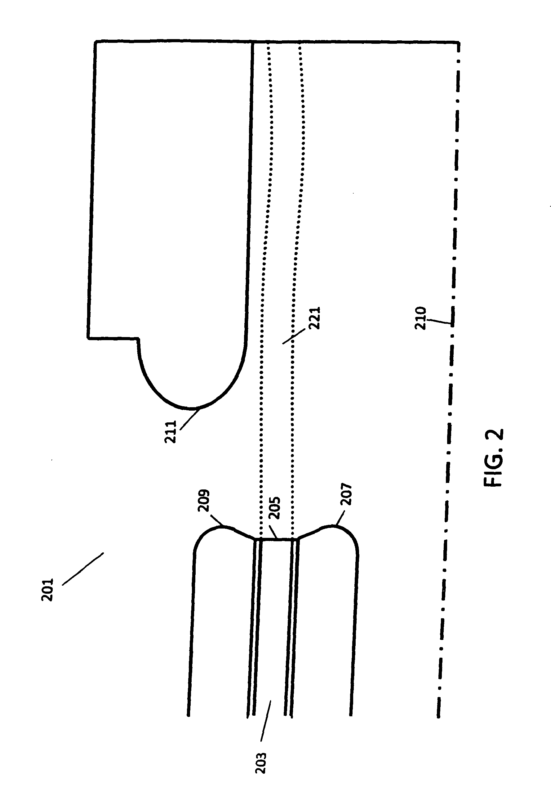
A klystron has a hollow beam electron gun that has a circular planar electron emitting surface. A hollow electron beam is directed from the electron gun through a plurality of drift tubes, resonant chambers and magnetic fields to a collector. The hollow electron beam does not experience significant radial movement and can operate at a lower beam voltage which reduces the required length of the RF interaction circuit and lowers the risks of RF arcing.

Description

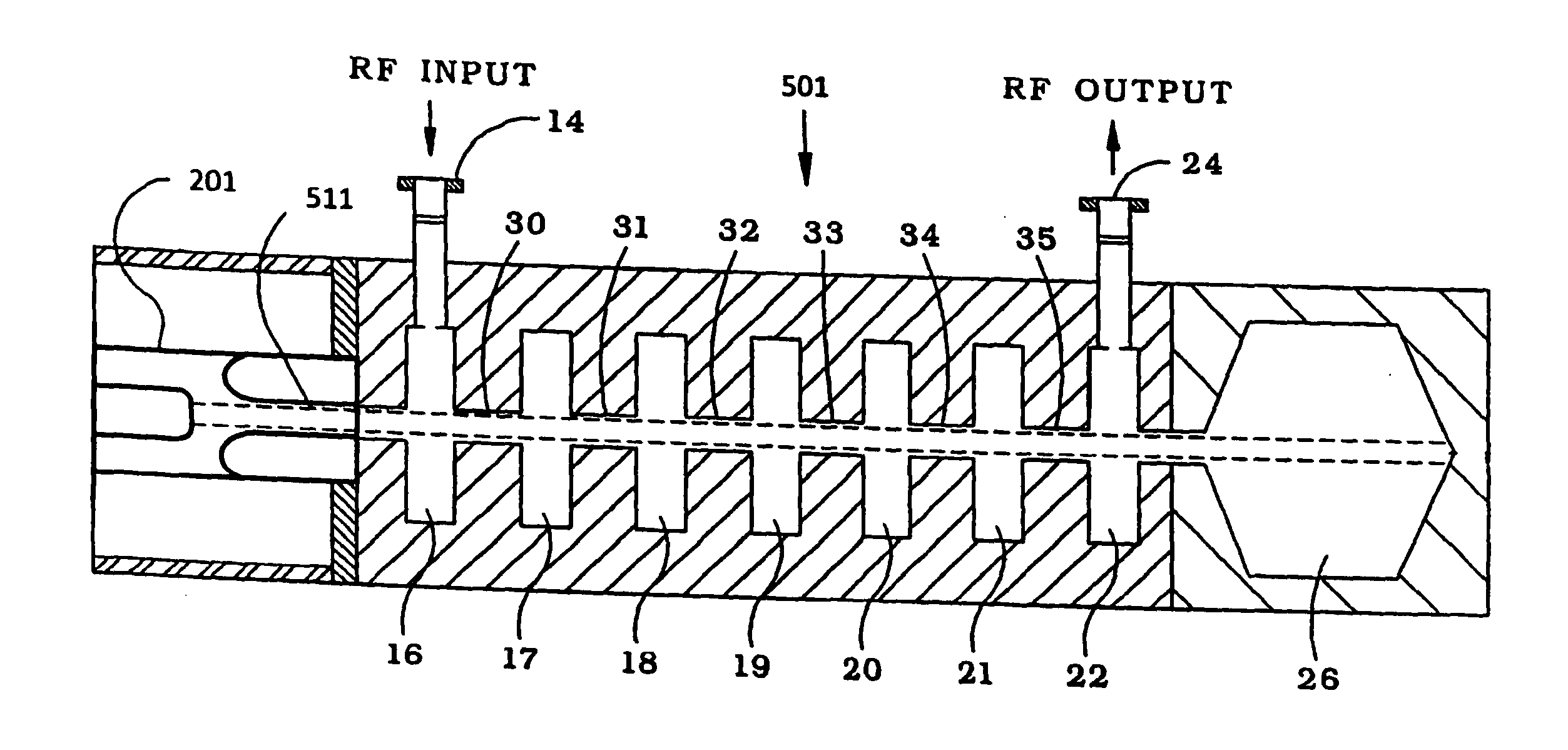
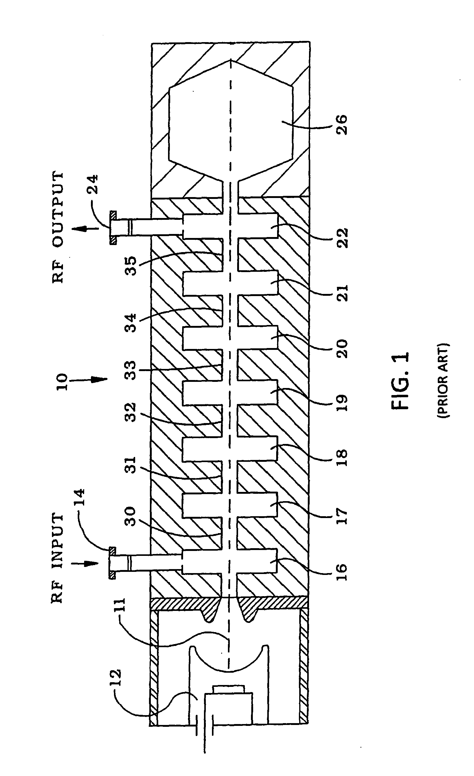
FIELD OF INVENTION[0001]The present invention relates generally to hollow beam electron guns used with multiple cavity klystrons. These klystrons can be used for particle accelerators and colliders, power amplifier for radar and directed energy applications.BACKGROUND OF THE INVENTION[0002]FIG. 1 is a schematic view of a conventional seven-cavity klystron 10. The klystron 10 amplifies RF energy by extracting energy from an electron beam. A plurality of successive drift tubes 30, 31, 32, 33, 34, 35 respectively connect with the seven cavities 16, 17, 18, 19, 20, 21, 22, such that one drift tube interconnects two adjacent cavities. Each cavity is individually tuned, and an electromagnet is placed around the klystron for focusing the electron beam. The electron gun 12 produces an electron beam 11 which is accelerated to a high voltage. Simultaneously, a microwave signal is fed into an RF input port 14 for interacting with the electron beam 11 within an input resonating cavity 16. The e...

Claims


Application Information

Patent Timeline
Patent Type & Authority Applications(United States)
IPC IPC(8): H01J23/08H01J29/48
CPCH01J25/14H01J23/06
Inventor FERGUSON, PATRICK
Owner FERGUSON PATRICK
Learn More