Capacitor module

a technology of capacitors and modules, applied in the direction of electrolytic capacitors, electrical apparatus construction details, transportation and packaging, etc., can solve the problems of large amount of heat generation of capacitors, large variation of load applied to capacitors, and rapid deterioration of capacitors, so as to improve the strength of the entire module, improve the strength of the heat dissipating body, and high degree of freedom

Inactive Publication Date: 2011-01-13
KOMATSU LTD
View PDF17 Cites 34 Cited by
  • Summary
  • Abstract
  • Description
  • Claims
  • Application Information

AI Technical Summary

Benefits of technology

[0014]According to the invention, since the second closed-bottomed screw hole is provided on the surface different from the surface on which the flow passage for causing the cooling medium to flow is formed of the surfaces of the heat-dissipating body for screwing the cell-fixing body for fixing the capacitor cells to the heat-dissipating body, the strength of the heat-dissipating body may be improved as compared to a case in which the through hole is formed on the heat-dissipating body. Also, since the second screw hole does not pass through the heat-dissipating body, limitation regarding the shape of the flow passage is less as compared to a case in which the second screw hole passes through the heat-dissipating body. Therefore, the capacitor module capable of improving the strength of the entire module and having the high degree of freedom when designing the cooling medium flow passage may be provided.

Problems solved by technology

When applying the capacitor module as the storage device of a hybrid construction machine as an example of the hybrid vehicle, since the construction machine frequently repeats drive and deceleration every few seconds to several tens of seconds, variation of load applied to the capacitor is large and an amount of heat generation of the capacitor easily becomes large.
Therefore, there is a problem that the capacitor rapidly deteriorates and lifetime of the capacitor is short.

Method used


Image

  • Capacitor module
  • Capacitor module
  • Capacitor module

Examples


Embodiment Construction

[0072]Hereinafter, a best mode for carrying out the invention (hereinafter, referred to as an “embodiment”) is described with reference to the attached drawings. Meanwhile, the drawings referred to in a following description are schematic ones, and a dimension, a scale and the like of a material might differ in different drawings.

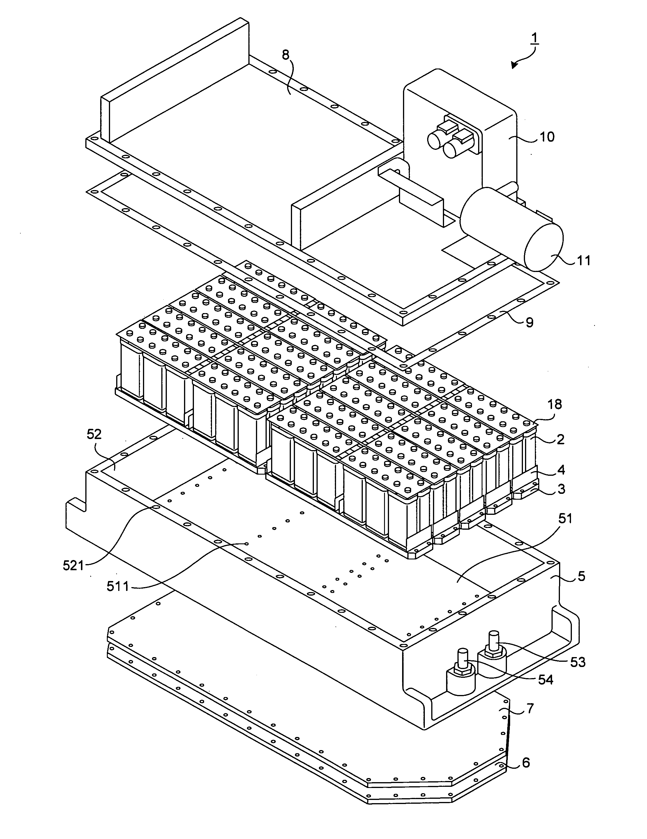
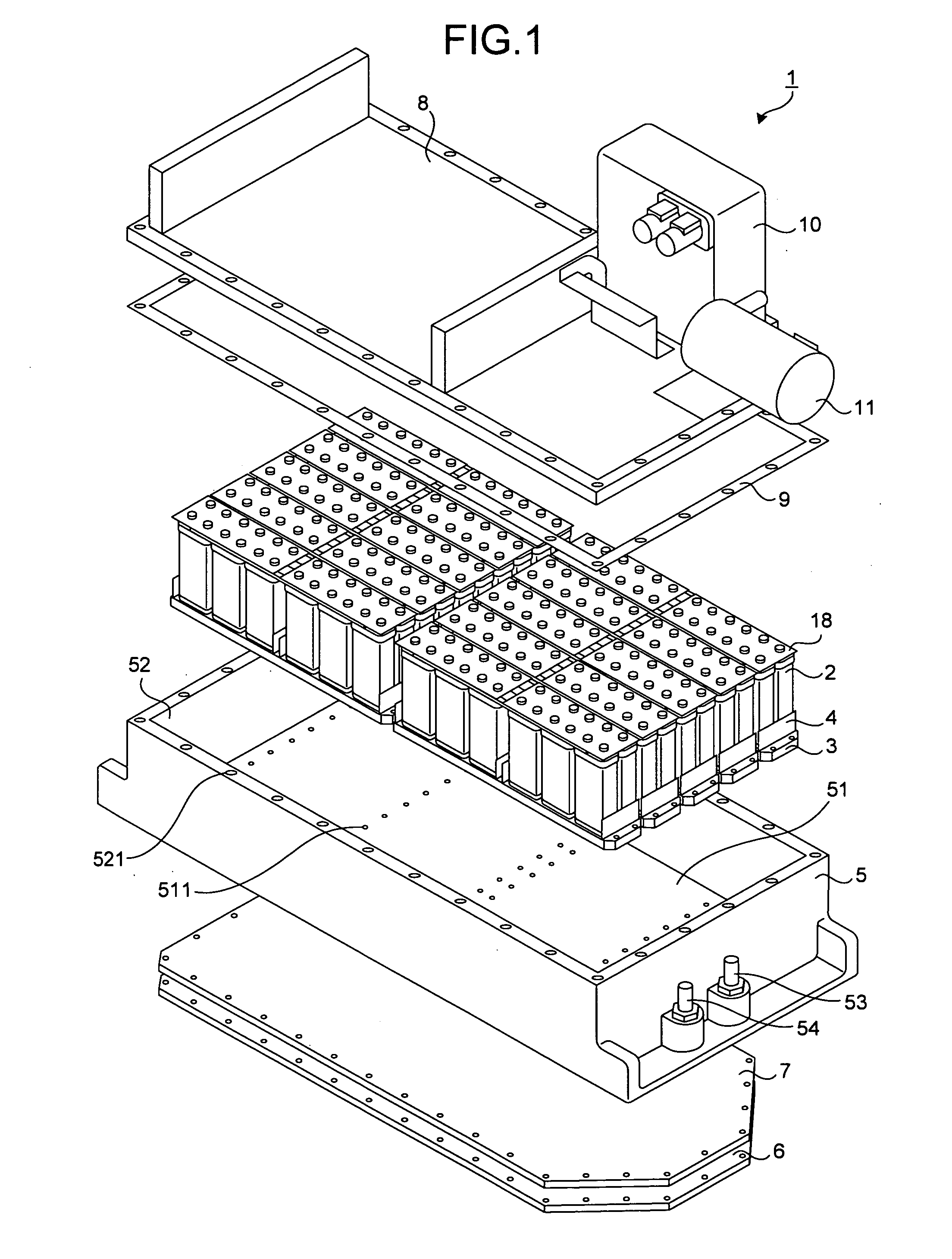
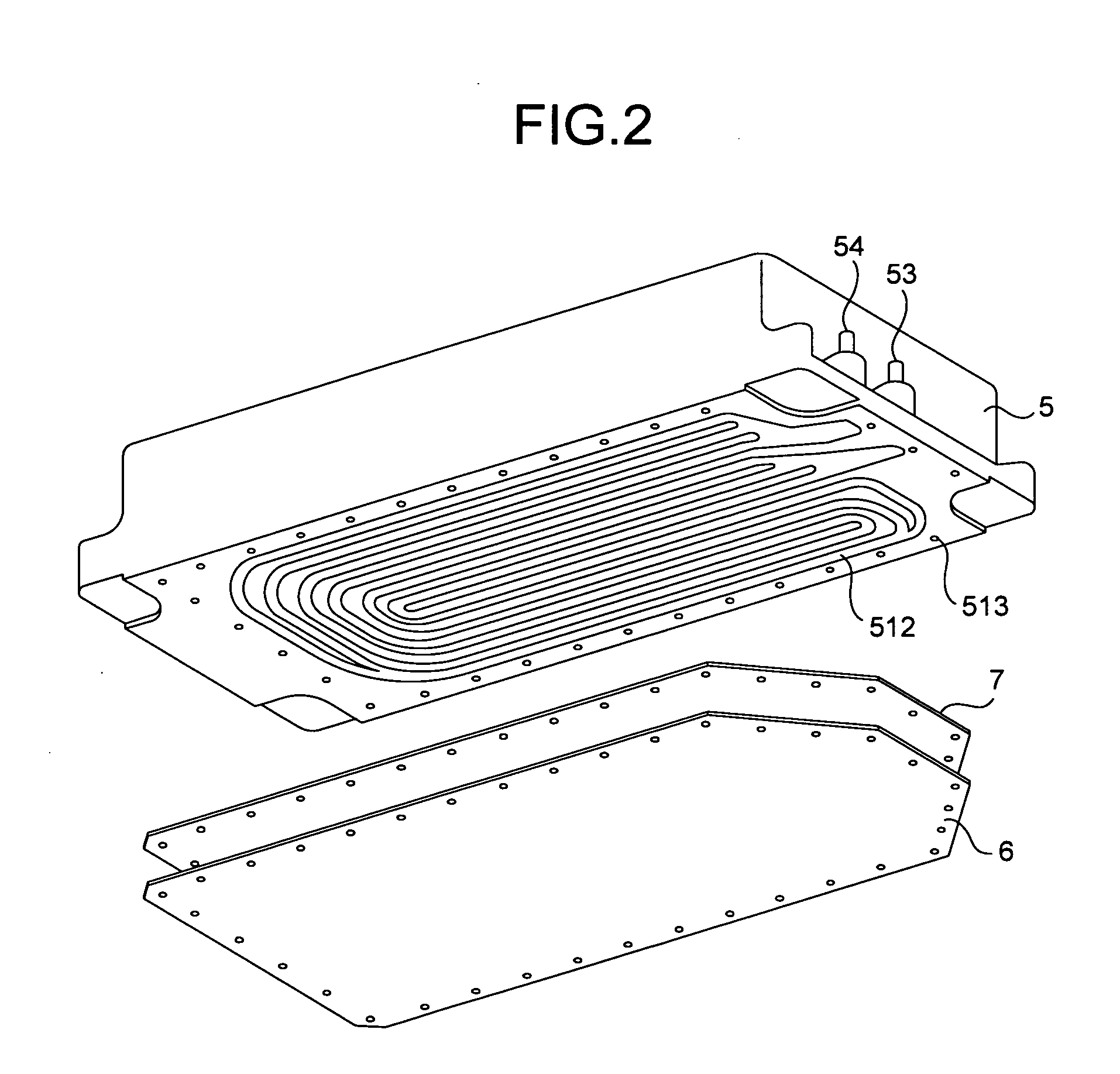
[0073]FIG. 1 is an exploded perspective view illustrating a configuration of a capacitor module according to one embodiment of the invention. FIG. 2 is a view illustrating a schematic configuration of a bottom of a casing of the capacitor module according to this embodiment. FIG. 3 is a partial cross-sectional view of a substantial part of the capacitor module seen in a cross-sectional plane parallel to a longitudinal direction of the capacitor module according to this embodiment. FIG. 4 is a partial cross-sectional view of the substantial part of the capacitor module seen in a cross-sectional plane parallel to a lateral direction of the capacitor module ac...


PUM


Abstract

A capacitor module is provided with a plurality of capacitor cells each having a capacitor and a capacitor case provided with a first closed-bottomed screw hole with an opening on a bottom surface for housing the capacitor, a metallic cell-fixing body having a through-hole in communication with the first screw hole to which the capacitor cells are fixed by inserting a cell screw in the through-hole and the first screw hole, an insulator made of a thermally conductive insulating material and provided between the capacitor cells and the cell-fixing body for insulating the capacitor cells from the cell fixing body, and a metallic heat-dissipating body having a second closed-bottomed screw hole in which a cell-fixing body screw is inserted and having a flow passage for causing a cooling medium to flow on a rear surface side of a surface on which the second screw hole is provided.

Description

TECHNICAL FIELD[0001]The invention relates to a capacitor module provided with a plurality of capacitor cells each of which houses a capacitor.BACKGROUND ART[0002]A hybrid vehicle equipped with an engine and a generator motor as driving sources is provided with a storage device for storing electricity generated by the generator motor driven by the engine. The storage device also has a function as a power supply for supplying electricity to the generator motor. As such storage device, a capacitor module provided with a large-capacity capacitor is sometimes applied.[0003]When applying the capacitor module as the storage device of a hybrid construction machine as an example of the hybrid vehicle, since the construction machine frequently repeats drive and deceleration every few seconds to several tens of seconds, variation of load applied to the capacitor is large and an amount of heat generation of the capacitor easily becomes large. Therefore, there is a problem that the capacitor ra...

Claims


Application Information

Patent Timeline
Patent Type & Authority Applications(United States)
IPC IPC(8): H05K7/20
CPCB60K6/28B60K6/46B60Y2200/25B60Y2200/412H01G2/04H01G2/08H01G9/155Y02E60/13Y02T10/6217Y02T10/7022H01G9/0003Y02T10/62Y02T10/70H01G11/10H01G11/18H01G11/82
Inventor SOUDA, AKIHIKO
Owner KOMATSU LTD
Why Eureka
Try Eureka