Gun Drill

Inactive Publication Date: 2011-01-13
YUNITAKKU
View PDF16 Cites 4 Cited by
  • Summary
  • Abstract
  • Description
  • Claims
  • Application Information

AI Technical Summary

Benefits of technology

[0005]The present invention was made in view of the foregoing circumstances, and accordingly it is an object of the present invention to provide a gun drill capable of supplying a coolant sufficiently to a cutting region even when a cutting blade or a guide pad is of a brazed type, or when an opening angle of a cutting chip discharge groove is large or when a tool diameter is small and of achieving high cutting efficiency by discharging cutting chips efficiently from the cutting region.

Problems solved by technology

However, if a gun drill is configured such that a tip made of a hard material such as cemented carbide, ceramic, cermet, etc., is brazed as the cutting blade of the cutting head or the guide pad in order to increase cutting performance and processing accuracy or such that an opening angle of the cross-sectionally V-shaped cutting chip discharge groove is set large in order to increase discharge performance of the cutting chips, a cross section of a thickness portion at a distal end side of a cutting head main body becomes small, and a large hole diameter of the coolant supply passage cannot be obtained for securing strength as a cutting tool.
As a result, a coolant supply amount to the cutting region is limited, and thus increasing cutting efficiency becomes difficult.
In particular, the smaller a tool diameter is, the more likely it is to disadvantageously lead to a deficiency in coolant supply.

Method used


Image

  • Gun Drill
  • Gun Drill
  • Gun Drill

Examples


first embodiment

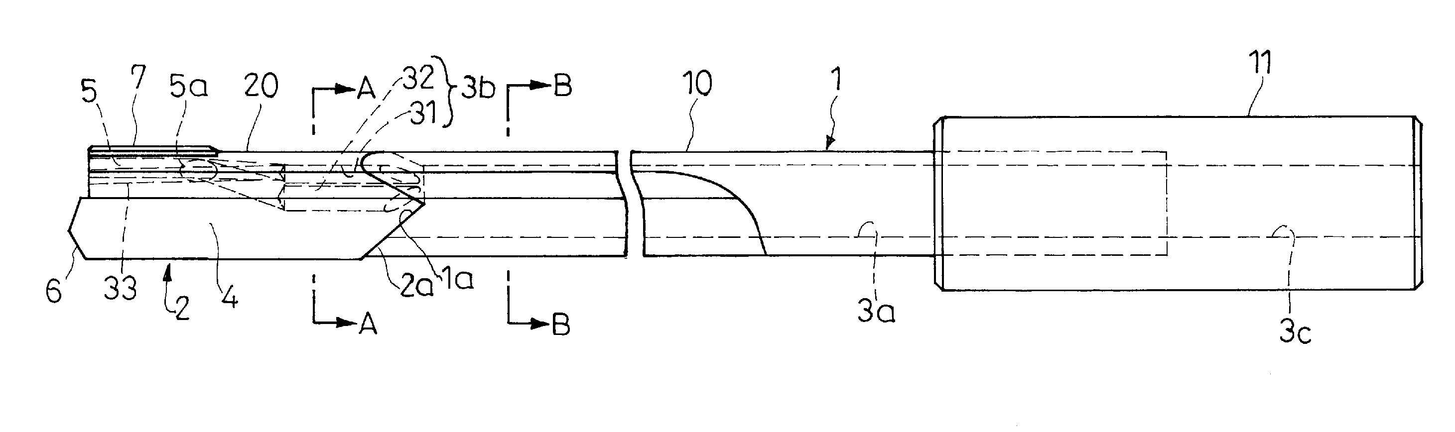
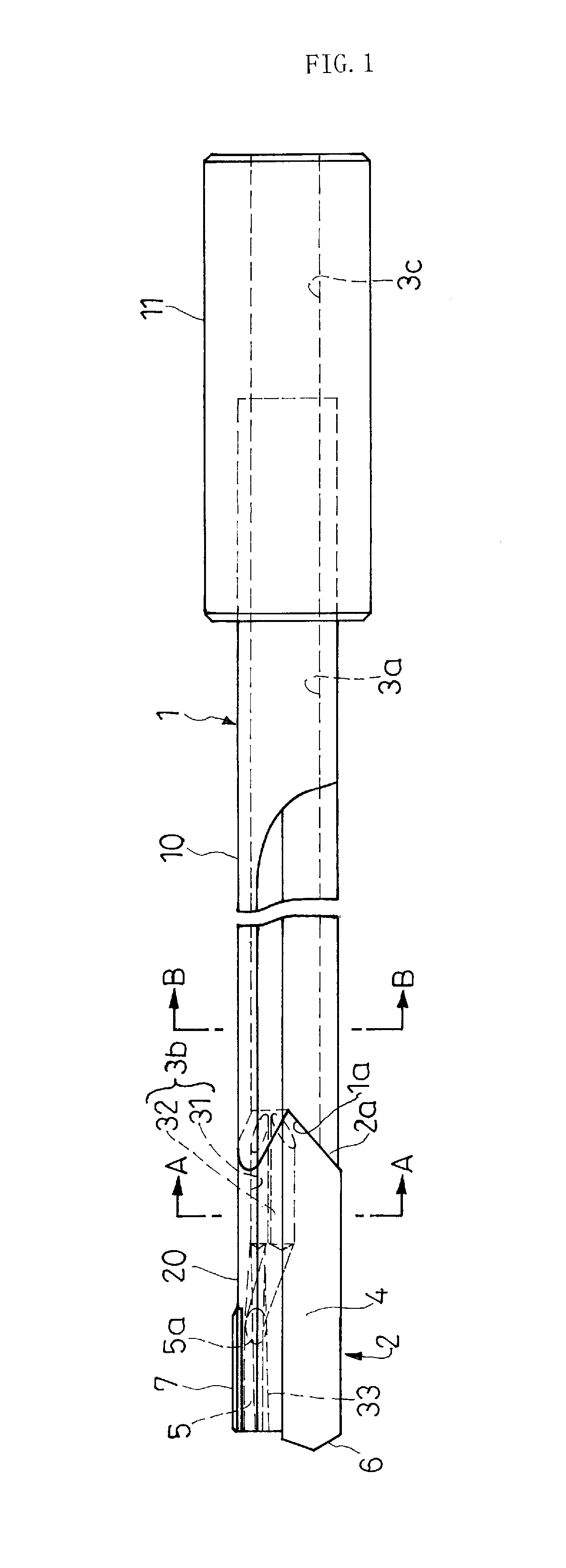
[0045]As shown in FIG. 1, a gun drill of the first embodiment is composed of an elongated tool shank 1 made of a pipe material 10 such as steel and having a distal end 1a cut in a V-shape, a cutting head 2 having a proximal end 2a cut in a corresponding inverted V-shape (mountain-shape) and brazed to the distal end 1a to be concentrically coupled, and a large-diameter cylindrical driver 11 insertedly fitted and fixed with a proximal end portion of the tool shank 1. The gun drill also includes one lengthwise direction linear cutting chip discharge groove 4 on an outer circumferential surface extending from a proximal side of the tool shank 1 to the cutting head 2 distal end. The cutting chip discharge groove 4 forms a V-shape in cross section whose opening angle from the center of the tool shank 1 and the cutting head 2 is approximately 110 to 130 degrees.

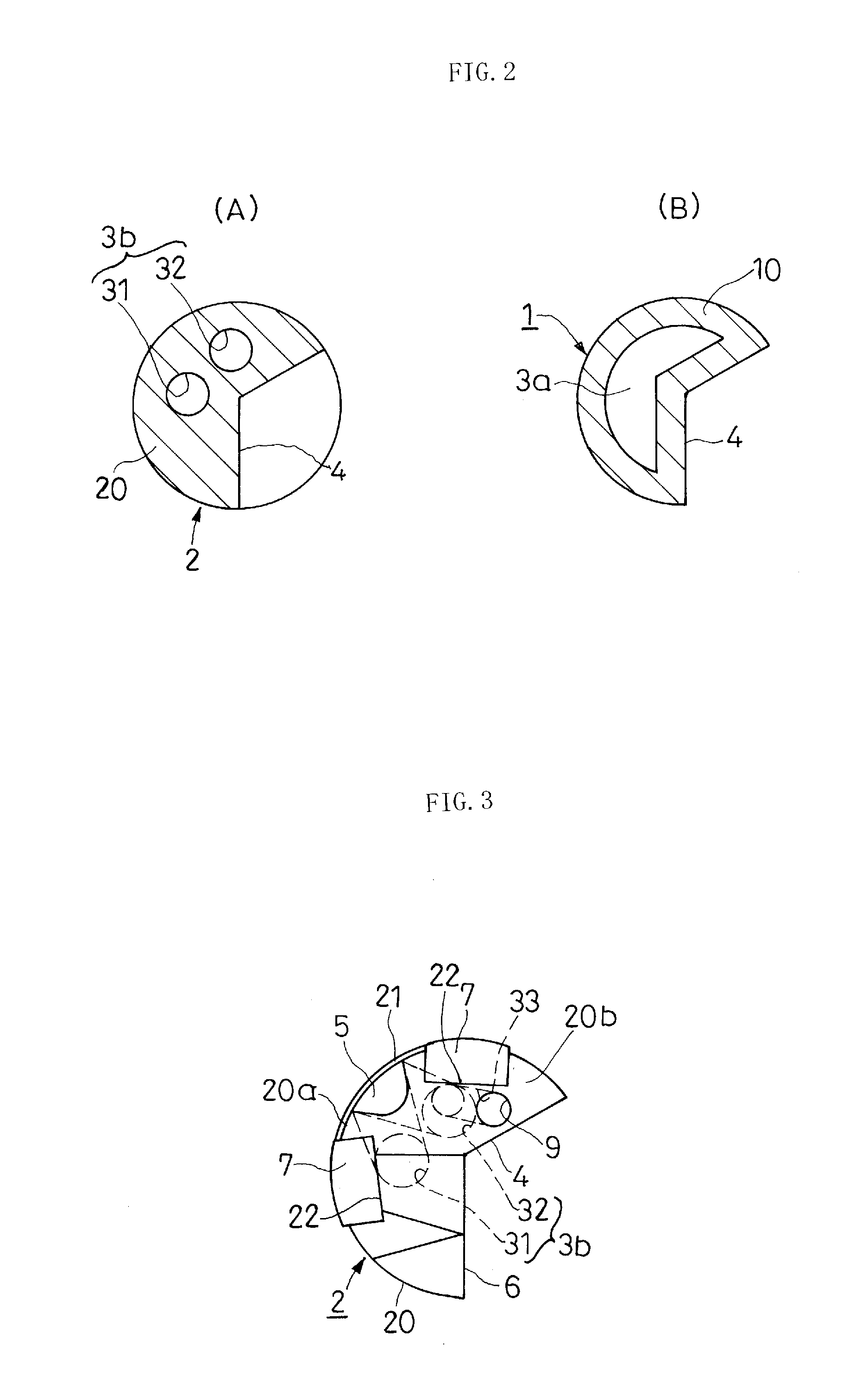
[0046]The tool shank 1 is formed so as to have a cross section of a two-thirds circle as shown in FIG. 2B by die-forming the pipe ...

second embodiment

[0052]In the second embodiment, the head main body 20 is made of steel such as general tool steel, and a hard material such as cemented carbide, sintered ceramics, cermet, etc., is used for the guide pad 7 and the cutting blade tip 8. Again, the guide pad 7 and the cutting blade tip 8 are fitted into recessed portions 22, 23 provided in advance to the head main body 20 and are brazed by a metalizing method.

[0053]In deep-hole drilling by the above-described gun drills of the first and the second embodiment, the coolant supplied through the coolant supply passages 3a, 3b within the tool shank 1 and the cutting head 2 is led out mainly from the coolant lead-out port 5a provided on the outer circumferential surface portion 20a of the cutting head 2 to the coolant lead-out groove 5, through which the coolant is discharged to the cutting region. Part of the supplied coolant passes from one of the coolant circulation holes 32 of the coolant supply passage 3b through the circulation hole 33...


PUM

PropertyMeasurementUnit
Angleaaaaaaaaaa
Diameteraaaaaaaaaa
Efficiencyaaaaaaaaaa

Abstract

A gun drill is capable of supplying a coolant sufficiently to a cutting region even when a cutting blade or a guide pad is of a brazed type, or when an opening angle of a cutting chip discharge groove is large or when a tool diameter is small and of achieving high cutting efficiency by discharging cutting chips efficiently from the cutting region. The gun drill includes coolant supply passages inside a tool shank and inside a cutting head. A lengthwise direction linear cutting chip discharge groove on an outer circumferential surface extends from a proximal side of the tool shank to a cutting head distal end. The cutting head is formed with a coolant lead-out groove extending from a head-lengthwise direction intermediate portion to the head distal end, at an outer circumferential surface portion at a back side relative to the cutting chip discharge groove. A coolant lead-out port communicating with a coolant supply passage is open at a proximal end side of the coolant lead-out groove.

Description

RELATED APPLICATIONS[0001]This is 371 U.S. National Phase Application of PCT / JP2008 / 070901, filed 18 Nov. 2008, which claims priority to JP 2008-066252, filed 14 Mar. 2008. The contents of the aforementioned applications are incorporated by reference in their entirety.TECHNICAL FIELD[0002]The present invention relates to a gun drill used for deep-hole drilling.BACKGROUND[0003]As a deep-hole drilling system, various systems such as a gun drill system, an ejector system (double tube system), a single tube system, etc., have been known, and the gun drill system is suitable for deep-hole drilling of a small diameter. More specifically, as shown, for example, in FIG. 7, the gun drill system generally adopts a gun drill having a cutting head 52 which is provided at the distal end of a hollow took shank 51 of a two-thirds to three-quarters circle in cross section and has the same cross-sectional outline. The gun drill carries out cutting while supplying a coolant, which is supplied through...

Claims


Application Information

Patent Timeline
IPC IPC(8): B23B51/06
CPCB23B51/06Y10T408/45B23B2251/424B23B51/066
Inventor NOMURA, TAKUJI
Owner YUNITAKKU
Why Eureka
Try Eureka