
Fluorescent Anti-counterfeit fiber of which optical color is variable with irradiation angle of exciting light and Anti-counterfeit material

a technology of exciting light and anti-counterfeit materials, which is applied in the direction of dye addition to spinning solution, non-fibrous pulp addition, synthetic resin layered products, etc., can solve the problems of counterfeiters easily keeping away from the difficult and complicated paper making process, the influence of counterfeiters is not easily recognized, and the world's difficult problems have not been solved, so as to reduce the influence, reduce or even eliminate the influence

Inactive Publication Date: 2011-01-13
SHANGHAI KOS SECURITY PAPER TECH CO LTD
View PDF4 Cites 21 Cited by
  • Summary
  • Abstract
  • Description
  • Claims
  • Application Information

AI Technical Summary

Benefits of technology

[0078]1. This invention solves the universal problem that the visual characteristic of fluorescence anti-counterfeit fiber is easy to be imitated by the printing filament. Adopting this invention can prevent the counterfeit from rounding the superior difficulty papermaking threshold.
[0079]2. In this invention, the inventor skillfully makes use of two materials that have different heat shrinkage to creatively solve the problem of directional bending anti-counterfeit fiber, which makes the operation of directional curving fiber more convenient.
[0080]3. This invention adopts the design that every component is transparent by visible light in order to make naked eye be able to conveniently observe the obvious effect of optical color variable with irradiation angles of fluorescence anti-counterfeit fiber from any angle.
[0081]4. Based on the profound understand of the existing situation of spinning equipment, this invention designs straight anti-counterfeit fiber with oblate cross section (D / H≧1.5) exhibiting optical color variable with irradiation angles (only the visual difference from luminescent color M to N). This kind of fiber could only be made by three-component spinning equipment. However, the spinning equipment does not exist now, and it must be specialized made so that the equipment corresponding to such structure could be owned exclusively. This is good for controlling the source of the fiber producing, and furthermore increasing the effect of anti-counterfeiting.
[0082]5. The color changing of said fiber exhibiting optical color variable with irradiation angles does not only relies on the shape of three-dimensional section formed by fiber components, but also relies on the irradiation direction of the exciting light. So when the anti-counterfeit fiber falls into the layer of paper pulp, it faces two limits. The first limit is that the pressure of papermaking would make anti-counterfeit fiber's cross section oblate. The second limit is that the more paper fibers cover said fluorescent anti-counterfeit fibers, the larger the influence of the diffuse reflection of paper fiber on the direction changing of the exciting light, because the diffuse reflection of paper fiber around fluorescent anti-counterfeit fibers to the exciting light can change exciting light direction In order to reduce the influence of the above two factors, the inventor adopts and selects many special design of fiber cross section in this invention by repeating experiment and analysis, to reduce or even eliminate the influence of the above two factors and make it able to apply in practice.

Problems solved by technology

The fluorescent anti-counterfeit fiber paper has been widely used in the field of bank notes, passports, stamps and a variety of securities, but when counterfeiters print fine line with fluorescent ink to imitate visual characteristics of anti-counterfeit fiber paper, the naked eye can not distinguish them.
The direct consequences is that counterfeiters can easily keep away from the difficult and complicated paper making process, and use the most simple printing method for imitation.
This is a long-standing deficiency we have been eager to eliminate, but this world difficult problem has not been resolved for dozens of years.
In the same way, counterfeiter can mix shorter-wavelength fluorescent ink with longer-wavelength fluorescent ink, which have the same component, to print fine line having exactly the same visual effect with the above long and short band fluorescence fiber, so the problem of visual characteristics of fluorescent anti-counterfeit fibers being imitated by printing has not been solved.
The second, only when the effect of optical color variable with irradiation angles of light can still exist after papermaking, the value can be reflected, so the problem to be resolved at first is that fibers must have uniform orientation after papermaking.
This structure of the fibers has no practical value, and is easy to lead to erroneous judgment.
As the inventor of said patent appears to never know that the structure can produce the effect of optical color variable with irradiation angle of exciting light, so the above deduction is impossible.
The deeper the fluorescent fiber buried in the paper pulp, the more serious the adverse influence of diffuse reflection, and the worse the orientation of exciting light.
It will adversely affect the effect of optical variable with irradiation angles and result in the disappearance of the effect of optical color variable with irradiation angles.
If this question can not be overcome, it will be worthless for practical purpose.
It will adversely affect the effect of optical color variable with irradiation angles and result in the disappearance of this effect.
If it is not overcome, it will be worthless for practical purpose.

Method used


Image

  • Fluorescent Anti-counterfeit fiber of which optical color is variable with irradiation angle of exciting light and Anti-counterfeit material
  • Fluorescent Anti-counterfeit fiber of which optical color is variable with irradiation angle of exciting light and Anti-counterfeit material
  • Fluorescent Anti-counterfeit fiber of which optical color is variable with irradiation angle of exciting light and Anti-counterfeit material

Examples


embodiment 1

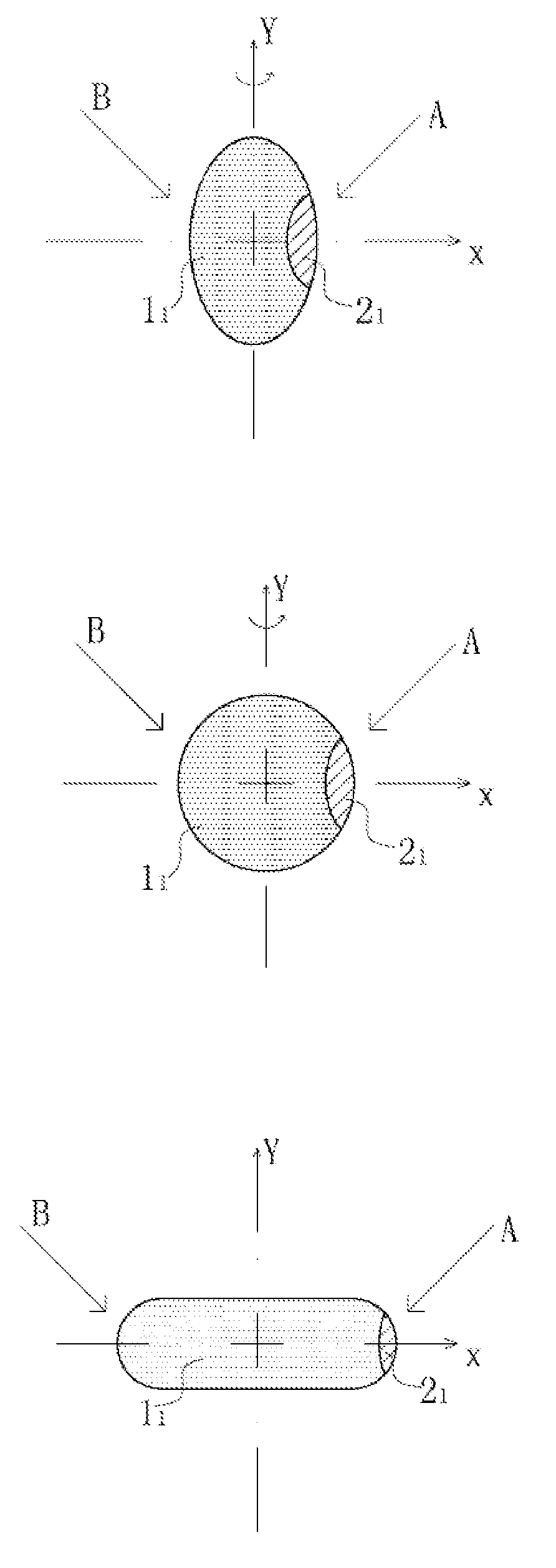
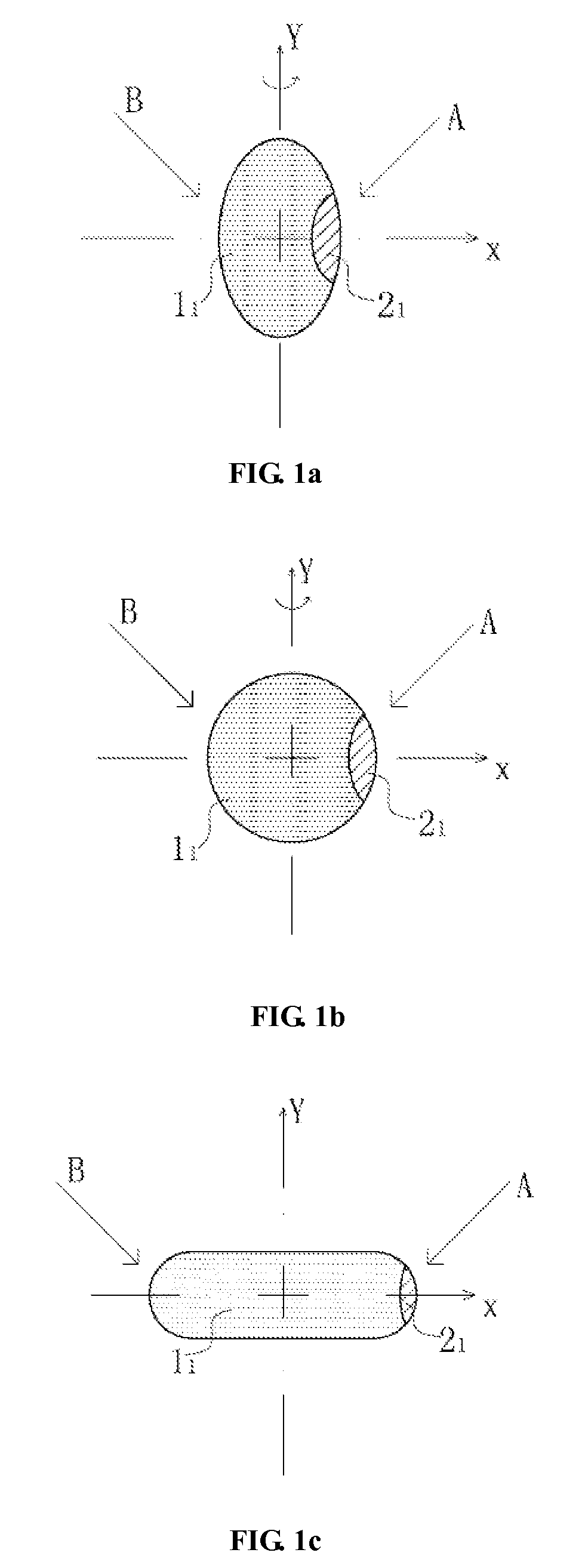
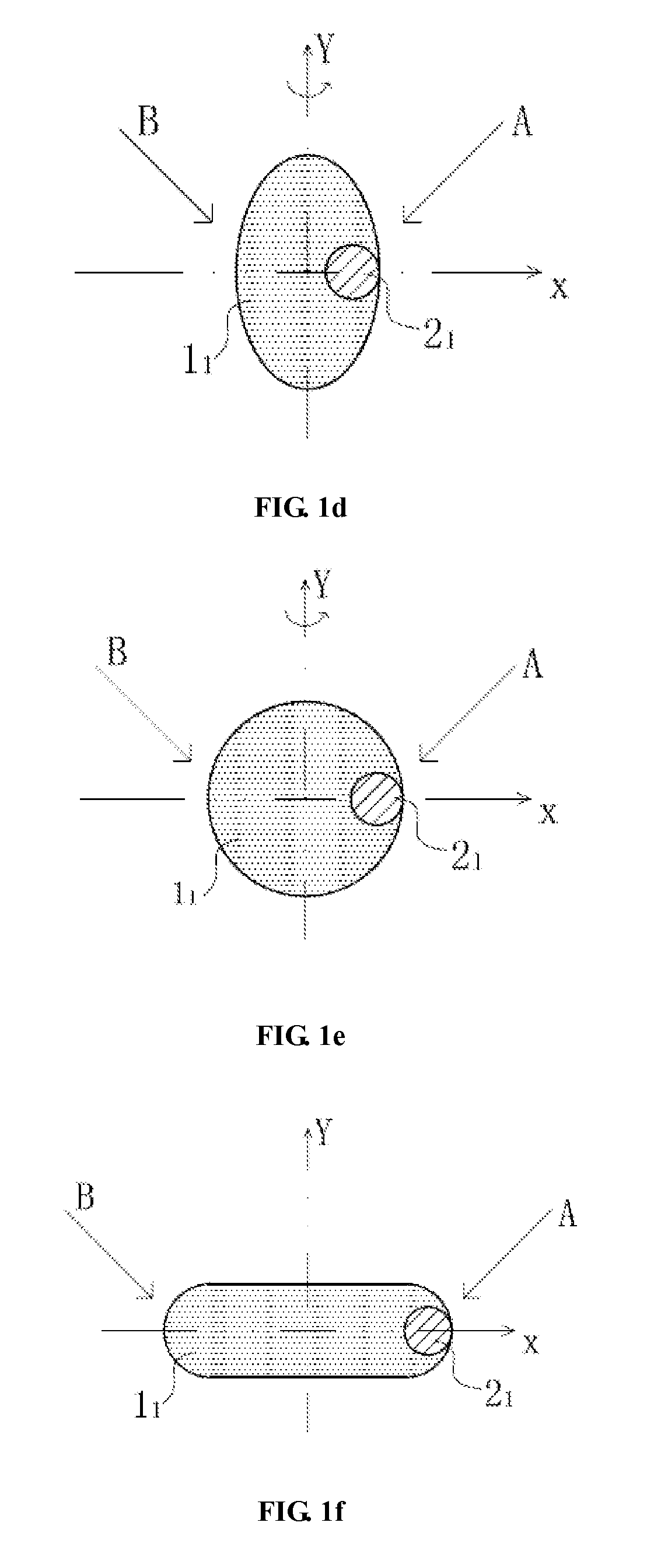
[0091]FIG. 1a, FIG. 1b, FIG. 1c, FIG. 1d, FIG. 1e and FIG. 1f show cross sections of two-component anti-counterfeit fiber which contains a component of photoluminescence material.

[0092]The cross section of the anti-counterfeit fiber comprises shielding component 1 and luminescent component 21. These two components are parallel distributed in the cross section and parallel extended without twisting to the longitudinal direction of the fiber. The shielding component does not contain photoluminescence material, but contains exciting light absorber which can be penetrable to visible light but shield exciting light. The absorption spectrum of absorbing material at least covers the excitation wavelength of the luminescent material. The luminescent component 21 contains photoluminescence material whose luminescent color is M which locates at the side of Y axis of the midperpendicular plane. The X axis which is the horizontal axis of cross section equally divides the cross section of photol...

embodiment 2

[0099]The fibers with cross sections as shown in FIG. 2a and FIG. 2b are parallel composed of the first luminescent component 22 and the second luminescent component 32. These two components are parallel distributed on the cross sections of anti-counterfeit fiber, and parallel extend in the longitudinal direction of the anti-counterfeit fiber without twisting. The cross-section flattening of anti-counterfeit fiber is ≦1, so said fiber is two-component curved fiber. The first luminescent component 22 contains photoluminescence material with luminescent color M. The second luminescent component 32 contains photoluminescence material with luminescent color N. And both of them have the same wavelength of exciting light, but luminescent color M and N are obviously different by naked eye. The two components locate respectively at the two sides of the Y axis of midperpendicular plane. The horizontal axis, X axis, of cross section equally divides the two parts located at midperpendicular pl...

embodiment 3

[0104]FIG. 3a, FIG. 3b, FIG. 3c, FIG. 3d, FIG. 3e and FIG. 3f show three-component anti-counterfeit fiber of which two components contain photoluminescence materials.

[0105]Said shielding component 13 is a light absorbing material which does not contain photoluminescence material and can be penetrable to visible light but shield the exciting light. The absorption spectrum of absorbing material covers the excitation wavelength of luminescent material. The first luminescent component 23 contains photoluminescence material with luminescent color M. The second luminescent component 33 contains photoluminescence material with luminescent color N. And both of them have the same wavelength of exciting light, but luminescent color M and N are obviously different by naked eye. On the cross-section of said fiber, the first luminescent component 23 and the second luminescent component 33 locate at two sides of Y axis. Preferably, said two luminescent components locate at two sides of Y axis sym...


PUM

PropertyMeasurementUnit
Shrinkageaaaaaaaaaa
Coloraaaaaaaaaa
Fluorescenceaaaaaaaaaa

Abstract

A fluorescent fiber and an anti-counterfeiting material have an optical color that varies with irradiation angles of exciting light. The anti-counterfeiting fiber includes at least two components of materials that extend parallel along the longitudinal direction without twisting. At least one component contains photoluminescence material. The distribution of the components makes the anti-counterfeit fiber form a shielding structure for exciting light, and has an orientation structure. The exciting light shielding structure and orientation structure enable, when the anti-counterfeit fiber falls freely into a plane paralleled to the horizontal plane, the existence of at least two irradiation angles of exciting light above the plane paralleled to the horizontal plane, from which exciting light irradiates on the anti-counterfeit fiber respectively. The anti-counterfeit fiber thereby displays obvious visual difference between two different luminescent colors. In this manner, the visual characteristic of fluorescent anti-counterfeit fiber cannot be imitated by the printing filament.

Description

FIELD OF THE INVENTION[0001]The present invention relates to a fluorescent anti-counterfeit fiber of which optical color can be variable with irradiation angle of exciting light and anti-counterfeit material containing said fluorescence anti-counterfeit fiber. More particularly, said fluorescent anti-counterfeit fiber and fluorescent anti-counterfeit fiber appeared on said anti-counterfeit material is the fluorescent fiber of which optical color varies with the irradiation angle of exciting light.BACKGROUND OF THE INVENTION[0002]The fluorescent anti-counterfeit fiber paper has been widely used in the field of bank notes, passports, stamps and a variety of securities, but when counterfeiters print fine line with fluorescent ink to imitate visual characteristics of anti-counterfeit fiber paper, the naked eye can not distinguish them. The direct consequences is that counterfeiters can easily keep away from the difficult and complicated paper making process, and use the most simple prin...

Claims


Application Information

Patent Timeline
IPC IPC(8): B32B27/04B32B5/00D21H21/40
CPCD01F1/06D01F1/10Y10T428/2929D21H21/40D21H21/48D01F8/04Y10T428/24994
Inventor SUN, XIANLIN
Owner SHANGHAI KOS SECURITY PAPER TECH CO LTD
Learn More