

Dispenser for local anaesthetics and other liquids
a liquid and local anaesthetic technology, applied in the direction of anaesthesia, hypothermia, packaged goods, etc., can solve the problems of sterility failure, jab accidents, no possibility of a more accurate dosing, etc., to reduce the risk of jab accidents and sterility failur
Inactive Publication Date: 2011-01-13
NIELSEN
View PDF37 Cites 24 Cited by
- Summary
- Abstract
- Description
- Claims
- Application Information
AI Technical Summary
Benefits of technology
[0010]The greatest advantages achieved by the invention are the possibility of a very precise and safe dosing by using the dispenser, and that an otherwise time-consuming procedure is simplified such that this procedure can be performed much quicker than it otherwise would.
[0040]Alternatively, the dispenser can be built together with the reservoir, whereby further reduction of jab accidents and sterility failure is achieved.Material
Problems solved by technology
This procedure implies a risk of sterility failure and jab accidents, and is time-consuming in addition.
Besides, there is no possibility of a more accurate dosing, as the driving out of the liquid occurs continually, and the dosing flow (measured as volume per second) depends on the applied force, the diameter of the used syringe, the length and inner diameter of the used needle, and finally of the resistance offered by the tissue.
There is no disclosure of a safety function if the hypodermic needle has been put in an unsuitable place where the fluid resistance impedes liquid transfer into the animal.
Method used
View moreImage
Smart ImageViewing Examples

Examples
first embodiment
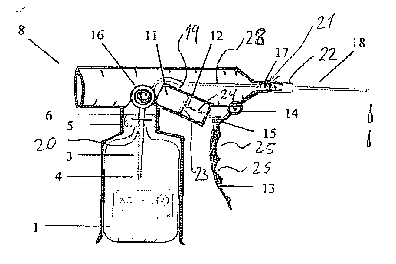
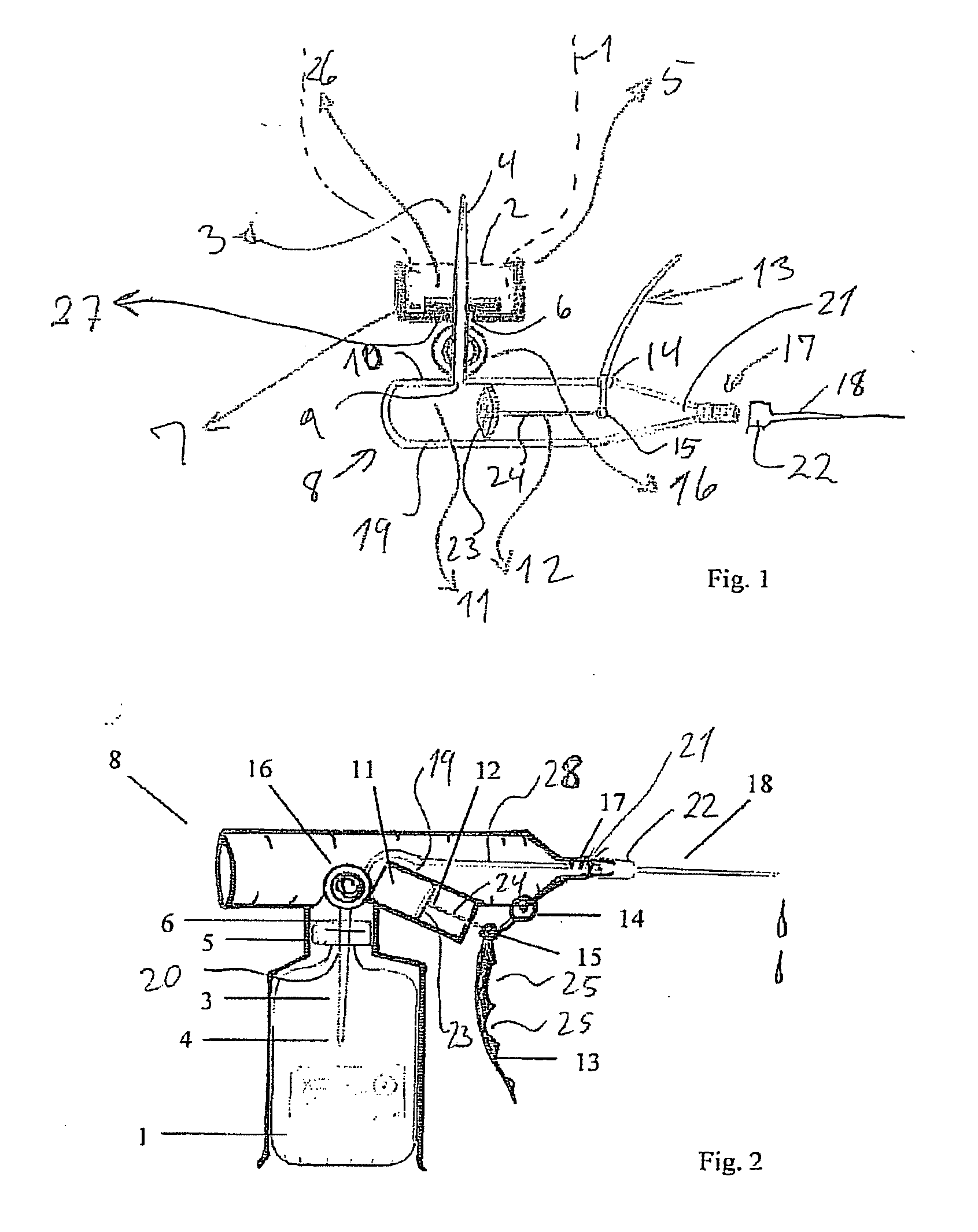
[0046]FIG. 1 illustrates the invention, where the reservoir is disposed with the opening down over the hypodermic needle, and where the pump grip is provided in a vertically upwards directed position;
second embodiment
[0047]FIG. 2 illustrates the invention, where the reservoir is disposed below the hypodermic needle and the pump grip is provided in a vertically downwards directed position;
third embodiment
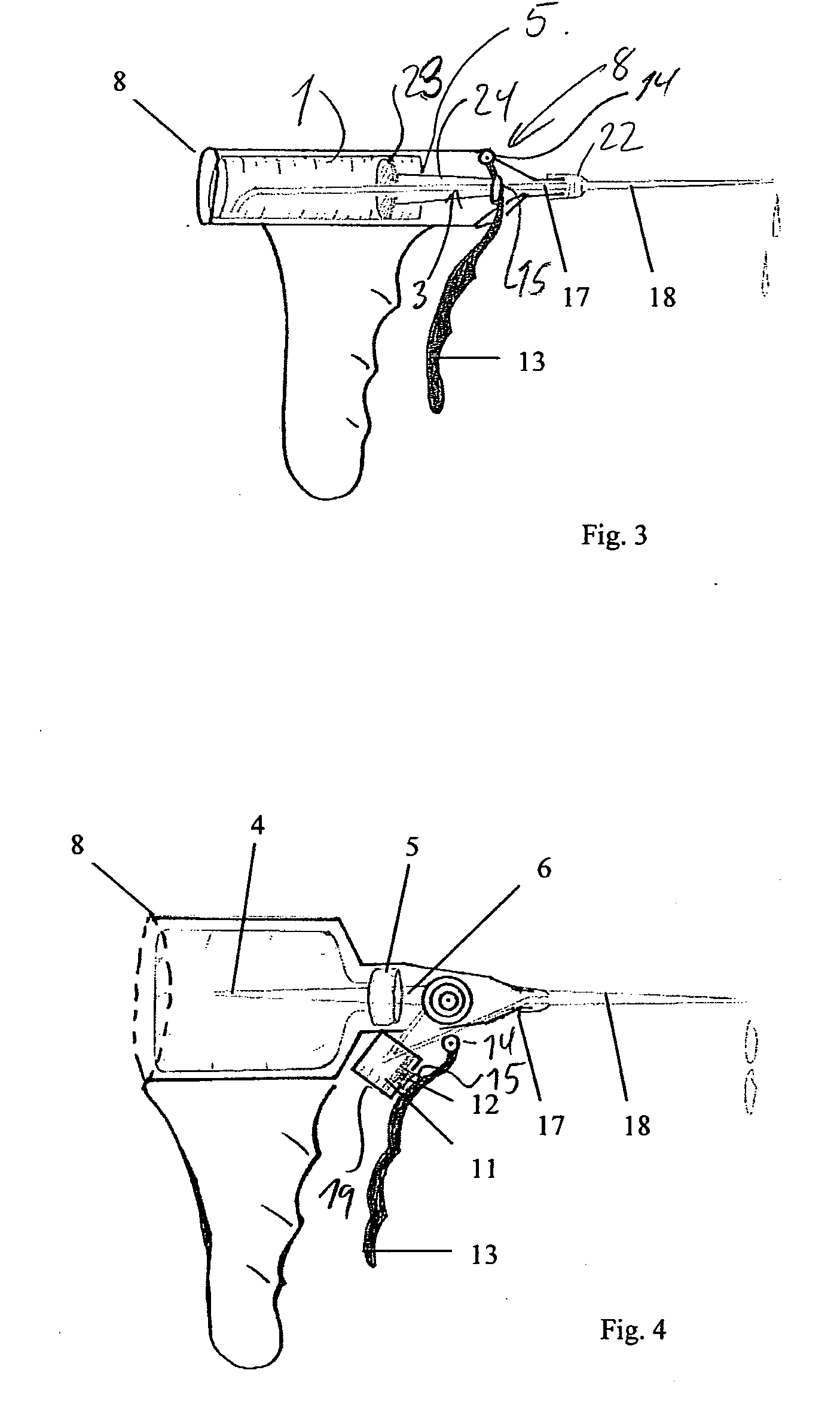
[0048]FIG. 3 illustrates the invention, where the pump grip is provided in a vertically downwards directed position; and
Login to View More PUM
 Abstract
A device for transferring liquid, e.g. local anesthetics, from a reservoir (1) to a hypodermic needle (18) for introduction into tissue. The device comprises a pump chamber (11) in a pump housing (19), which is provided with a manually displaceable pump piston (12), which is pivotably connected to a pump grip (13). The pump housing (19) is fluidly connected to the reservoir (1) through a piercing cannula (3) at an inlet (9), and fluidly connected to the needle (18) at an outlet (20).
Description
FIELD OF THE INVENTION[0001]The present invention concerns a device for transferring local anaesthetics from a reservoir to a hypodermic needle or a catheter which device includes a well-defined pump chamber in a pump housing which is provided with a manually displaceable pump piston which at one end outside the pump housing is provided with a pump grip, wherein the pump housing at an inlet has a first connection element for joining with a corresponding first connection element on the outlet of the reservoir, and wherein the pump housing has a second connection element at an outlet for joining with a corresponding second connection element on the needle or the catheter, and wherein the pump piston is connected via a piston rod with the pump grip which is pivotably suspended by joints, and which is actuated for transferring liquid from the reservoir to the hypodermic needle or the catheter for introducing the liquid into the tissue. The device is intended for use in the dispensing of...
Claims
Login to View More Application Information
Patent Timeline
 IPC IPC(8): A61M19/00A61M5/142
CPCA61J1/2096A61J2001/201A61M5/31581A61M5/3145A61M5/31525A61M5/204A61J1/201
InventorNIELSEN
OwnerNIELSEN