Protection-plate-attached electronic member

a technology of electronic components and plates, applied in the direction of discharge tubes luminescnet screens, printed circuit non-printed electric components association, instruments, etc., to achieve the effect of reducing the bonding strength

Inactive Publication Date: 2011-01-20
CASIO COMPUTER CO LTD +1
View PDF9 Cites 28 Cited by
  • Summary
  • Abstract
  • Description
  • Claims
  • Application Information

AI Technical Summary

Benefits of technology

[0007]According to an aspect of the present invention, there is provided a protection-plate-attached electronic member including: a first electronic member including a first transparent substrate; an adhesion layer which overlaps with the first transparent substrate; a protection plate fixed to the first electronic member in a state in which the adhesion layer intervenes between the protection plate and the first transparent substrate; and a peeling auxiliary section which intervenes between the adhesion layer and one of the protection plate and the first electronic member so as to lower bonding strength between the adhesion layer and the one of the protection plate and the first electronic member, wherein the adhesion layer includes an overlapping section which overlaps with the peeling auxiliary section; and a nonoverlapping section which does not overlap with the peeling auxiliary section and which directly contacts with the one of the protection plate and the first electronic member.

Problems solved by technology

However, because the joining strength between the display panel and the protection plate through the bonding agent or the adhesive compound is high, the display panel and the protection plate cannot be peeled from each other, and consequently it is a fact that the protection-plate-attached electronic member is obliged to be abandoned after all.

Method used


Image

  • Protection-plate-attached electronic member
  • Protection-plate-attached electronic member
  • Protection-plate-attached electronic member

Examples


first embodiment

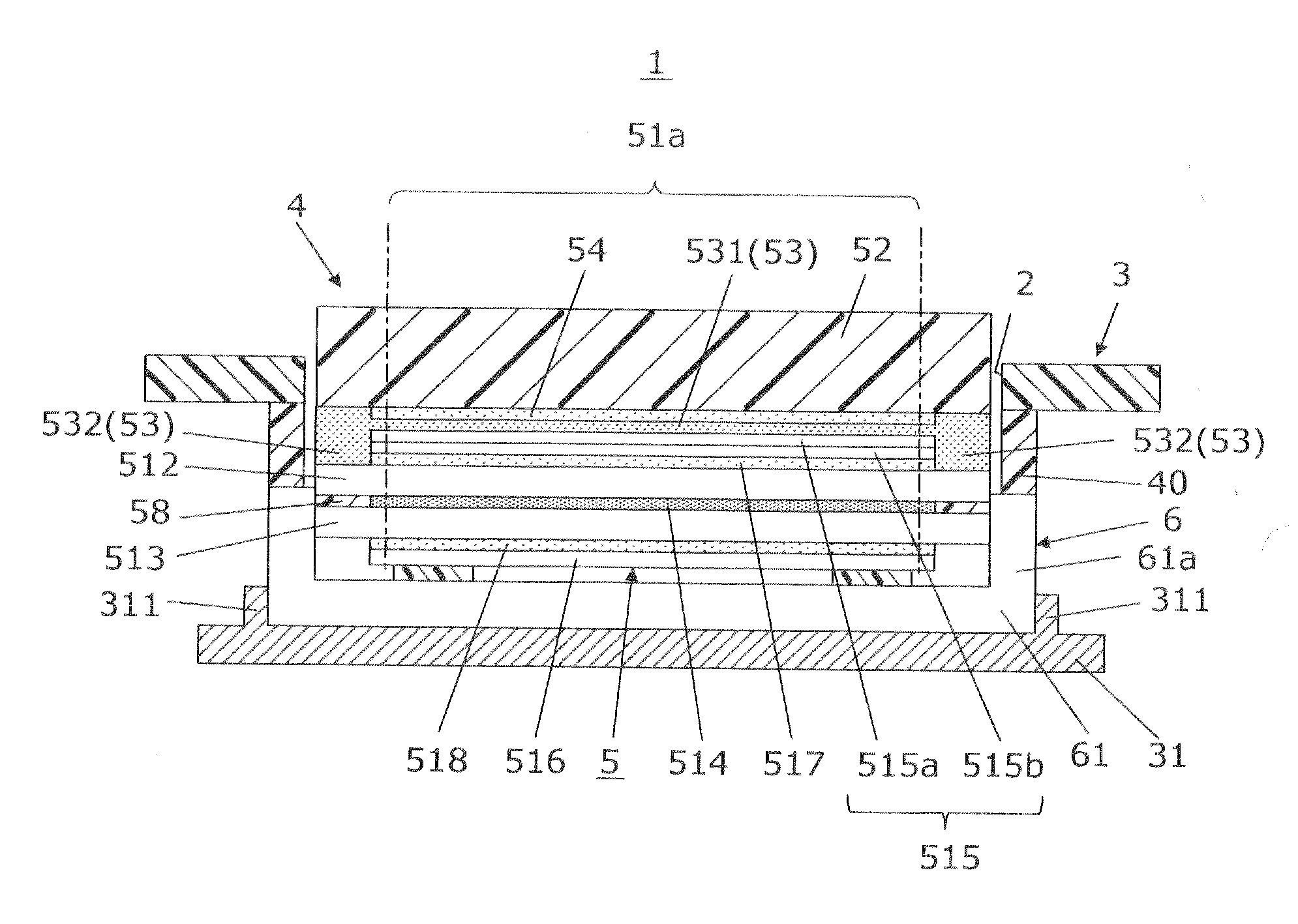
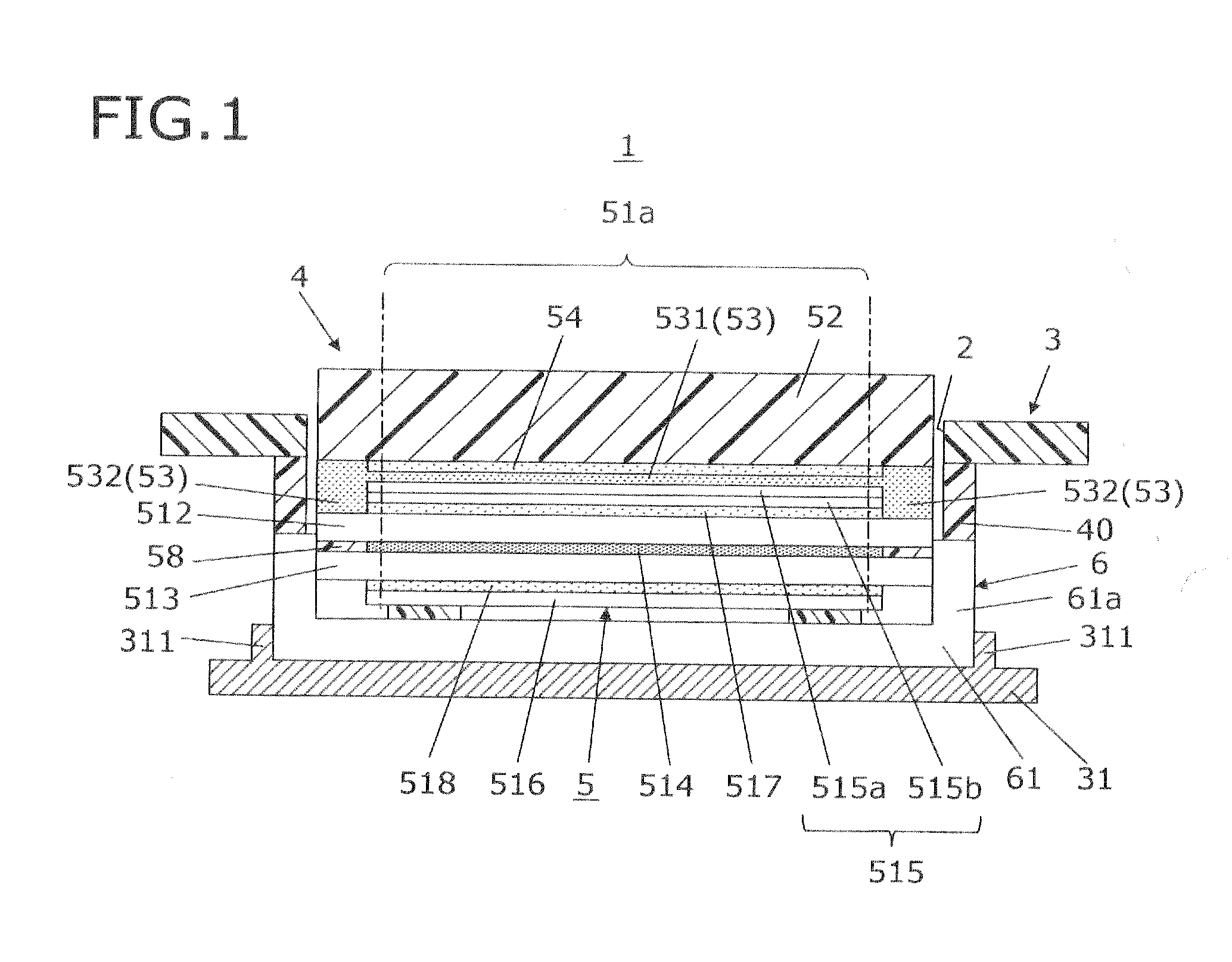
[0022]FIG. 1 is a sectional view showing the schematic configuration of an electronic apparatus, in which a protection-plate-attached electronic member according to a first embodiment of the present invention is mounted. An electronic apparatus 1 is a cellular phone handset, a digital camera, an electronic organizer, or the like. As shown in FIG. 1, the electronic apparatus 1 is equipped with a housing 3 including a displaying aperture 2 of a predetermined size, and a liquid crystal display module 4 housed in the housing 3 so as to correspond to the aperture 2.

[0023]The liquid crystal display module 4 includes a protection-plate-attached electronic member 5 and a surface light source unit 6 as a surface light source radiating an irradiating light to the protection-plate-attached electronic member 5. In the following, of sides of the protection-plate-attached electronic member 5, a side thereof on which the surface light source unit 6 is arranged (the lower side in FIG. 1) is called ...

second embodiment

[0046]Although the case of providing the protection plate 52 with the peeling auxiliary section 54 is illustrated in the first embodiment, a case of providing the liquid crystal display panel 51 with a peeling auxiliary section 54a is illustrated in a second embodiment. In the following, the same numerals are attached to the components, respectively, which are shared between the first embodiment and the second embodiment, and the descriptions thereof are omitted.

[0047]FIG. 6 is a sectional view showing the schematic configuration of a protection-plate-attached electronic member 5A according to the second embodiment. As shown in FIG. 6, in the protection-plate-attached electronic member 5A, a peeling auxiliary section 54a is arranged to overlap with the whole of the optical sheet 515 of the liquid crystal display panel 51. On the other hand, an adhesion layer 53a is directly laminated on the whole of a surface of the protection plate 52, the surface which is opposed to the liquid cry...

third embodiment

[0050]Although the case where the whole of the overlapping section 531 is enclosed by the nonoverlapping section 532 is illustrated in the first embodiment, a case where a part of an overlapping section is arranged on the outside of a nonoverlapping section is illustrated in a third embodiment. In the following, the same numerals are attached to the components, respectively, which are shared between the first embodiment and the third embodiment, and the descriptions thereof are omitted.

[0051]FIGS. 7A and 7B are explanatory views showing the schematic configuration of a protection-plate-attached electronic member 5B according to the third embodiment. FIG. 7A is a sectional view taken along the cutting-plane line VIIA-VIIA in FIG. 7B, and FIG. 7B is a sectional view taken along the cutting-plane line VIIB-VIIB in FIG. 7A. As shown in FIGS. 7A and 7B, a peeling auxiliary section 54b is provided with a first peeling auxiliary section 541b opposed to the optical sheet 515, and a second p...


PUM

PropertyMeasurementUnit
transparentaaaaaaaaaa
adhesionaaaaaaaaaa
bonding strengthaaaaaaaaaa

Abstract

A protection-plate-attached electronic member including: a first electronic member including a first transparent substrate; an adhesion layer which overlaps with the first transparent substrate; a protection plate fixed to the first electronic member in a state in which the adhesion layer intervenes between the protection plate and the first transparent substrate; and a peeling auxiliary section which intervenes between the adhesion layer and one of the protection plate and the first electronic member so as to lower bonding strength between the adhesion layer and the one of the protection plate and the first electronic member, wherein the adhesion layer includes an overlapping section which overlaps with the peeling auxiliary section; and a nonoverlapping section which does not overlap with the peeling auxiliary section and which directly contacts with the one of the protection plate and the first electronic member.

Description

CROSS-REFERENCE TO RELATED APPLICATIONS[0001]This application is based upon and claims the benefit of priority under 35 USC 119 of Japanese Patent Application No. 2009-165187 filed on Jul. 14, 2009, the entire disclosure of which, including the description, claims, drawings, and abstract, is incorporated herein by reference in its entirety.BACKGROUND OF THE INVENTION[0002]1. Field of the Invention[0003]The present invention relates to a protection-plate-attached electronic member.[0004]2. Description of the Related Art[0005]There is conventionally known a protection-plate-attached electronic member, for example, as disclosed in Japanese Patent Application Laid-Open Publication No. 2008-90053, the protection-plate-attached electronic member in which a protection plate is arranged on a side of the front surface of a display panel, and the protection plate and the display panel are bonded to each other for protecting the display panel. It is necessary for such a protection-plate-attach...

Claims


Application Information

Patent Timeline
Patent Type & Authority Applications(United States)
IPC IPC(8): G06F3/041H05K1/16G02F1/1333G02F1/1335H01J1/62
CPCG02F1/13338H01L51/5237G06F3/041G02F2201/50G06F1/1601H10K50/841H10K50/8445
Inventor TAKAHASHI, MASAYUKI
Owner CASIO COMPUTER CO LTD
Why Eureka
Try Eureka