Image display device, head-mounted display, and light beam expanding device
a display device and head-mounted display technology, applied in the direction of static indicating devices, instruments, optics, etc., can solve the problems of difficult to reduce the size of the image forming device, the size and weight of the image display device is also difficult, and achieve the effect of reducing the size and weigh
Active Publication Date: 2011-01-20
SONY CORP
View PDF6 Cites 41 Cited by
- Summary
- Abstract
- Description
- Claims
- Application Information
AI Technical Summary
Benefits of technology
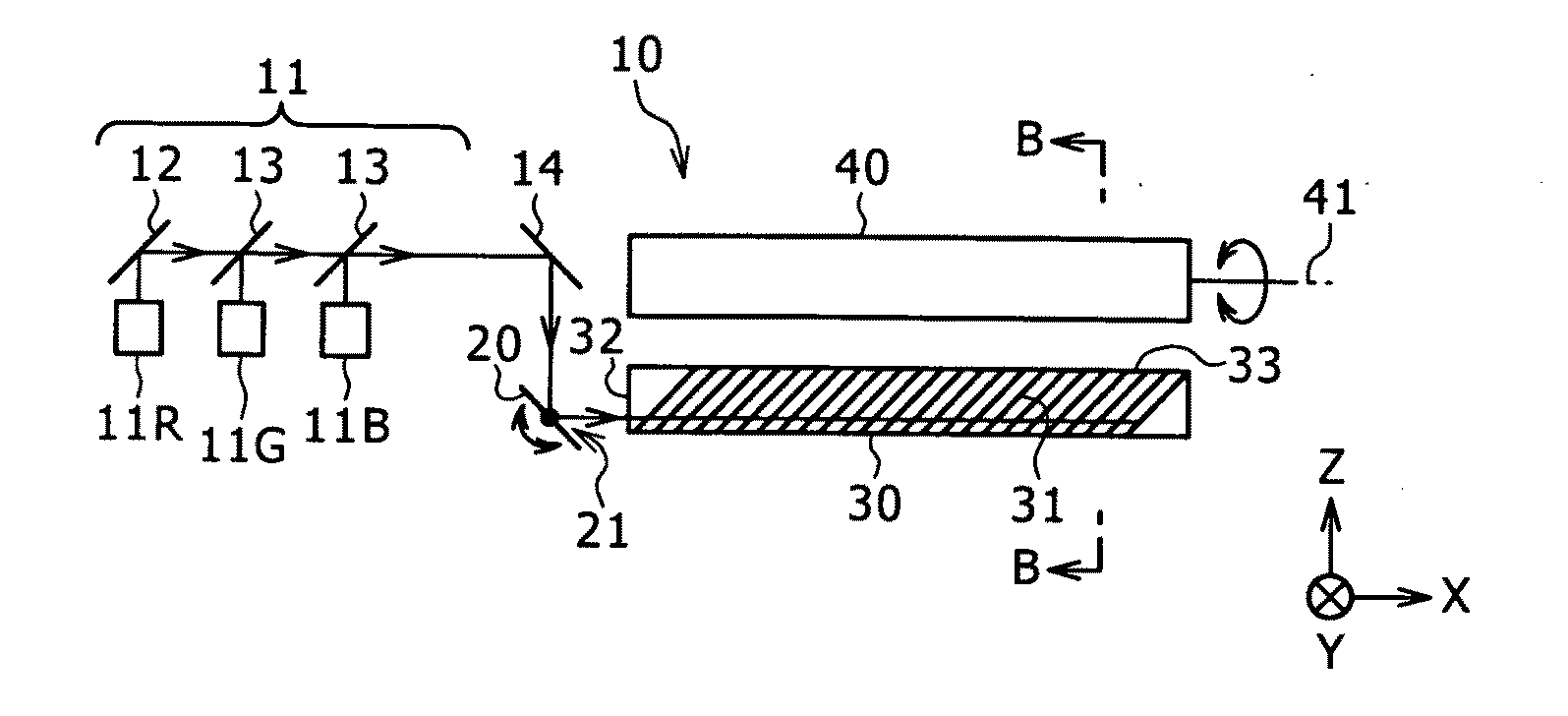
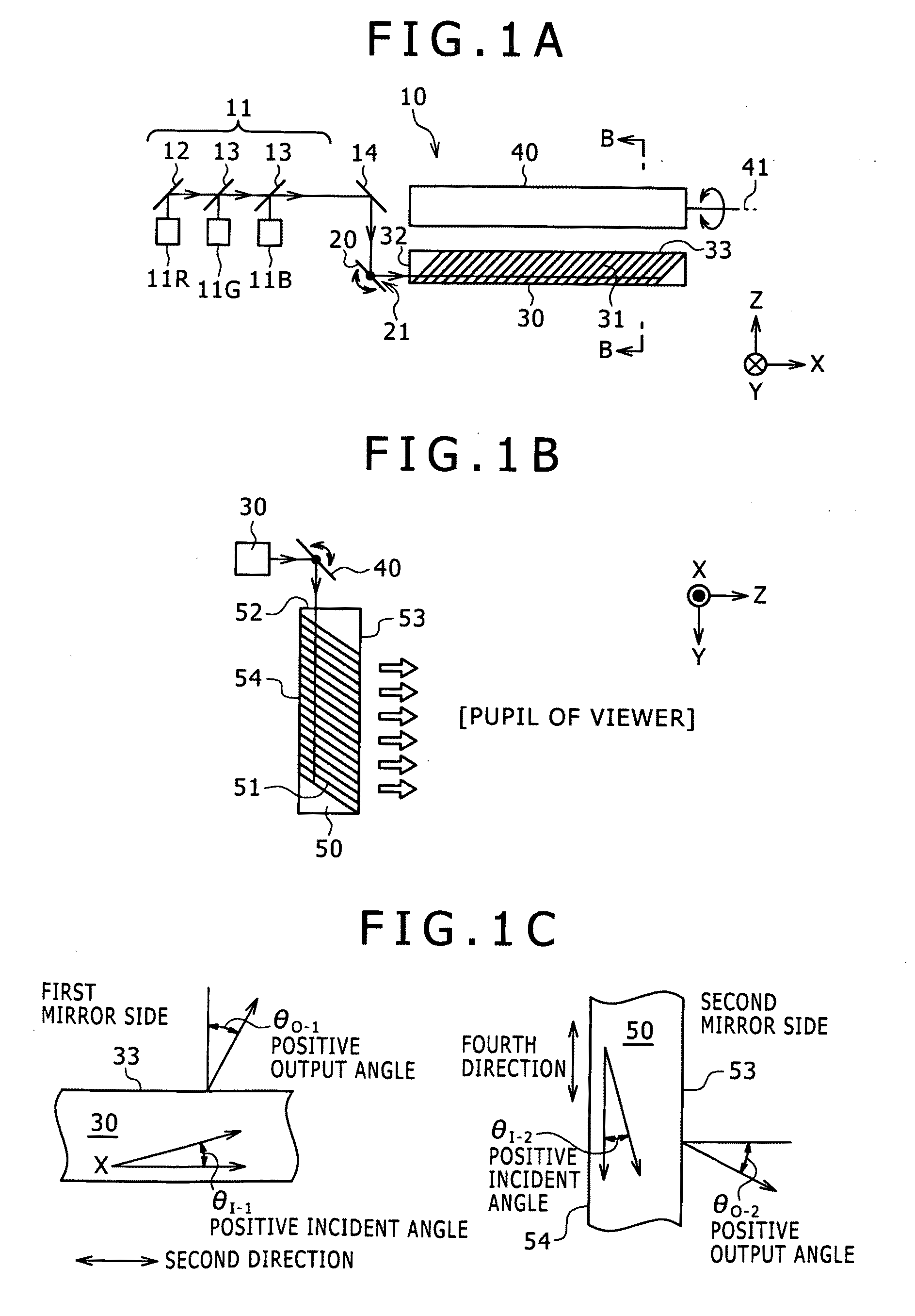
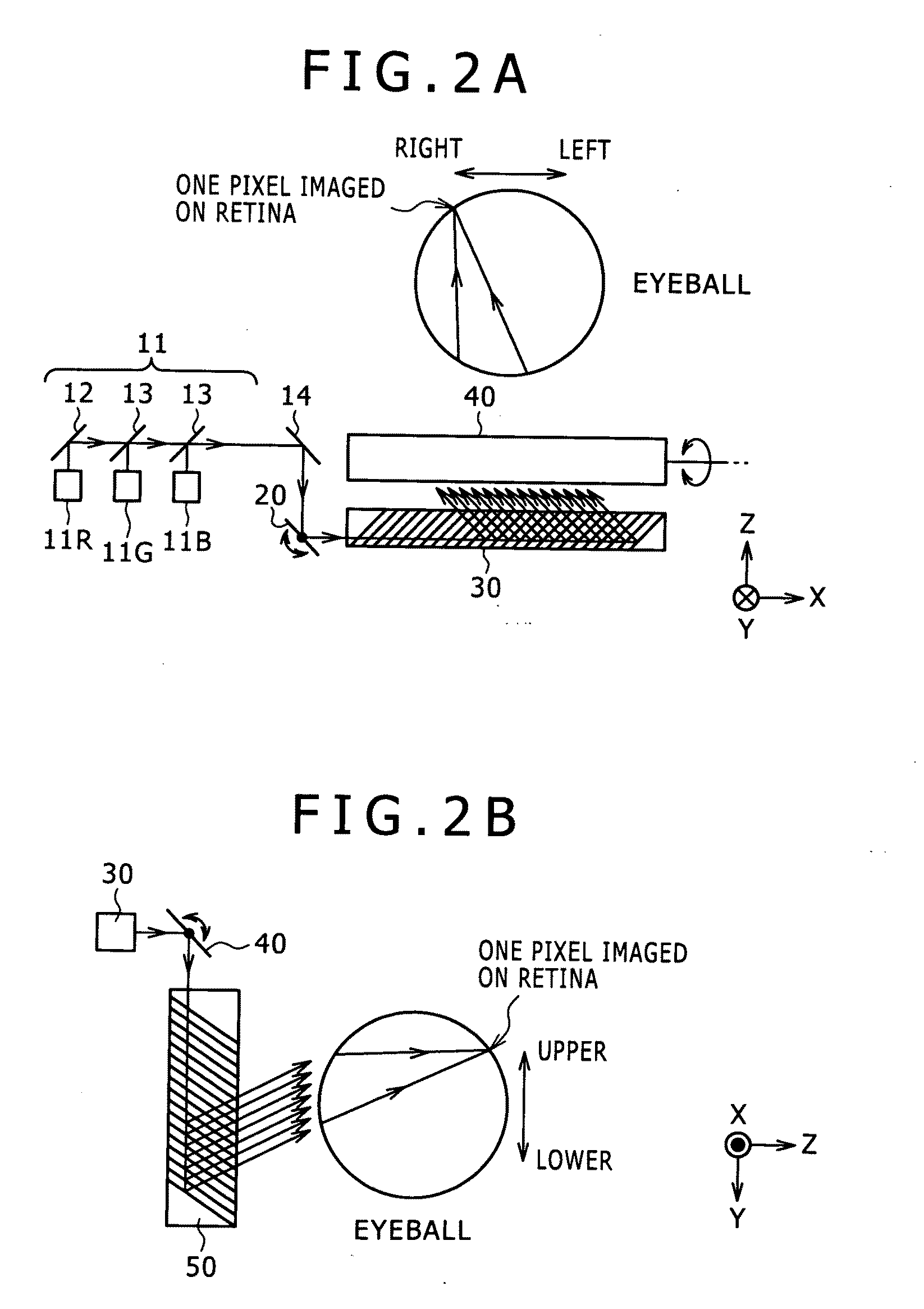
[0017]The image display device, the head-mounted display, and the light beam expanding device of the embodiments of the present invention include the first mirror, the first light deflector, the second mirror, and the second light deflector, and turn a light beam emitted from the light source to collimated light to output the collimated light. Therefore, the image forming device itself formed of e.g. a liquid crystal display device is unnecessary. In addition, for example a two-dimensional image does not need to be created as if it was an intermediate image inside the scanner or the light beam expanding device. That is, the imaging optical system is unnecessary. Consequently, reduction in the sizes of the light source and the scanner and reduction in the size and weight as the whole of the image display device can be achieved. In the image display device and the head-mounted display of the embodiments of the present invention, the collimated light that is originally emitted from the light source as a light beam and finally output from the second light deflector enters the eyeball of the viewer. Then the collimated light passes through the pupil (having a diameter of about 2 to 6 mm normally) in the eyeball and is imaged on the retina to be recognized as one pixel. This is because the light output from the second light deflector is collimated light. Repeating this operation plural times allows recognition of a two-dimensional image.
Problems solved by technology
Therefore, it is difficult to reduce the size of the image forming device 201.
Furthermore, because the image forming device 201 and the collimating optical system 202 are necessary in the image display device 200 of the related art, reduction in the size and weight as the whole of the image display device is also difficult.
Method used
View moreImage
Smart ImageViewing Examples
Examples
embodiment example 1 (
2. Embodiment Example 1 (Image Display Device and Light Beam Expanding Device)
embodiment example 2 (modification of embodiment example 1)
3. Embodiment Example 2 (Modification of Embodiment Example 1)
embodiment example 3 (another modification of embodiment example 1)
4. Embodiment Example 3 (Another Modification of Embodiment Example 1)
Login to View More PUM
 Abstract
Disclosed herein is an image display device including a light source and a scanner. The scanner includes (a) a first mirror on which a light beam emitted from the light source is incident, (b) a first light deflector on which the light beam output from the first mirror is incident and that outputs collimated light forming a first output angle depending on a first incident angle of the light beam in association with the pivoting of the first mirror, (c) a second mirror on which the collimated light output from the first light deflector is incident, and (d) a second light deflector on which the collimated light output from the second mirror is incident and that outputs collimated light forming a second output angle depending on a second incident angle of the collimated light in association with the pivoting of the second mirror.
Description
BACKGROUND OF THE INVENTION[0001]1. Field of the Invention[0002]The present invention relates to an image display device, a head-mounted display, and a light beam expanding device.[0003]2. Description of the Related Art[0004]A virtual-image display device (image display device) for allowing the viewer to view a two-dimensional image formed by an image forming device as an enlarged virtual image by a virtual-image optical system is known from e.g. JP-T-2005-521099 and Japanese Patent Laid-open No. 2006-162767.[0005]As shown in a conceptual diagram of FIG. 14, this image display device 200 includes an image forming device 201 including plural pixels arranged in a two-dimensional matrix, a collimating optical system 202 for turning light output from the pixels of the image forming device 201 to collimated light, and an optical guide unit 203 on which the light turned to the collimated light by the collimating optical system 202 is incident. The incident light is guided in the optical g...
Claims
Login to View More Application Information
Patent Timeline
 IPC IPC(8): G02B26/10
CPCG02B26/105G02B2027/015G02B27/0172
Inventor TANAKA, HIROSHIHAYASHIBE, KAZUYAYAMAGUCHI, MASANARISARUTA, KUNIHIKOISHIKAWA, KEITAIMAMURA, TEPPEI
Owner SONY CORP
Features
- R&D
- Intellectual Property
- Life Sciences
- Materials
- Tech Scout
- Unparalleled Data Quality
- Higher Quality Content
- 60% Fewer Hallucinations
Learn More Browse by: Latest US Patents, China's latest patents, Technical Efficacy Thesaurus, Application Domain, Technology Topic, Popular Technical Reports.
© 2025 PatSnap. All rights reserved.Legal|Privacy policy|Modern Slavery Act Transparency Statement|Sitemap|About US| Contact US: help@patsnap.com


