Aircraft engine protection device

Active Publication Date: 2011-01-27
THE CTFOT GROUP
View PDF9 Cites 8 Cited by
  • Summary
  • Abstract
  • Description
  • Claims
  • Application Information

AI Technical Summary

Benefits of technology

[0009]An illustrative embodiment of the invention envisions a jet engine guard device having three modules conferring progressive levels of impact protection to the engine air intake. Each of the guard modules is made of carbon fiber woven material and is formed so as to allow air to easily pass through the gaps in the weave, while providing intersections sufficient to prevent foreign bodies from passing through. Furthermore, carbon fiber allows the entire device to remain light weight. The engine protection device is designed as having a capture basket, which provides a tightly woven material body, touching the interior wall of the nacelle and extending into the interior volume. The capture basket is formed by a low wall of woven material joined to a high wall. In this configuration, material upon impacting the high wall is trapped between the low wall and high wall until it can be removed by maintenance personnel. The capture basket is able to catch foreign bodies as well as prevent interference with the engine turbines. The jet engine guard apparatus also has a tubular sleeve secured inside the nacelle with a second end that abuts the low wall of the basket and a first end that terminates before the opening of the nacelle. The engine protection device is configured, in part, to secure a first deflection screen located within the first end of the sleeve; as well as securing a second deflection screen located at the second end.

Problems solved by technology

While a direct strike on a fuselage is damaging to the airframe, the more pressing issue is when a bird strikes or other airborne hazard strikes the internal machinery of the engine assembly.
Bird or foreign body strikes can cause catastrophic engine failure, resulting in loss of control of the airplane and possibly a forced or emergency landing.
Currently, there is no effective device that both protects the engine while providing a non-lethal solution to prevent birds from entering the engine housing.
However, such devices and systems are known to limit engine thrust or create other problems with weight, maintenance, or cost.
While the Ghogomu prior art seeks to prevent foreign bodies from entering the engine intake, it does so in a manner that extends the profile of the engine, requires metal construction, and is capable of becoming a hazard itself if damaged.
While the device would clearly prevent foreign bodies from entering the engine intake, there are significant drawbacks.
Additionally, the guard is formed of metal and could pose a significant foreign body risk if damaged.

Method used


Image

  • Aircraft engine protection device
  • Aircraft engine protection device
  • Aircraft engine protection device

Examples


Embodiment Construction

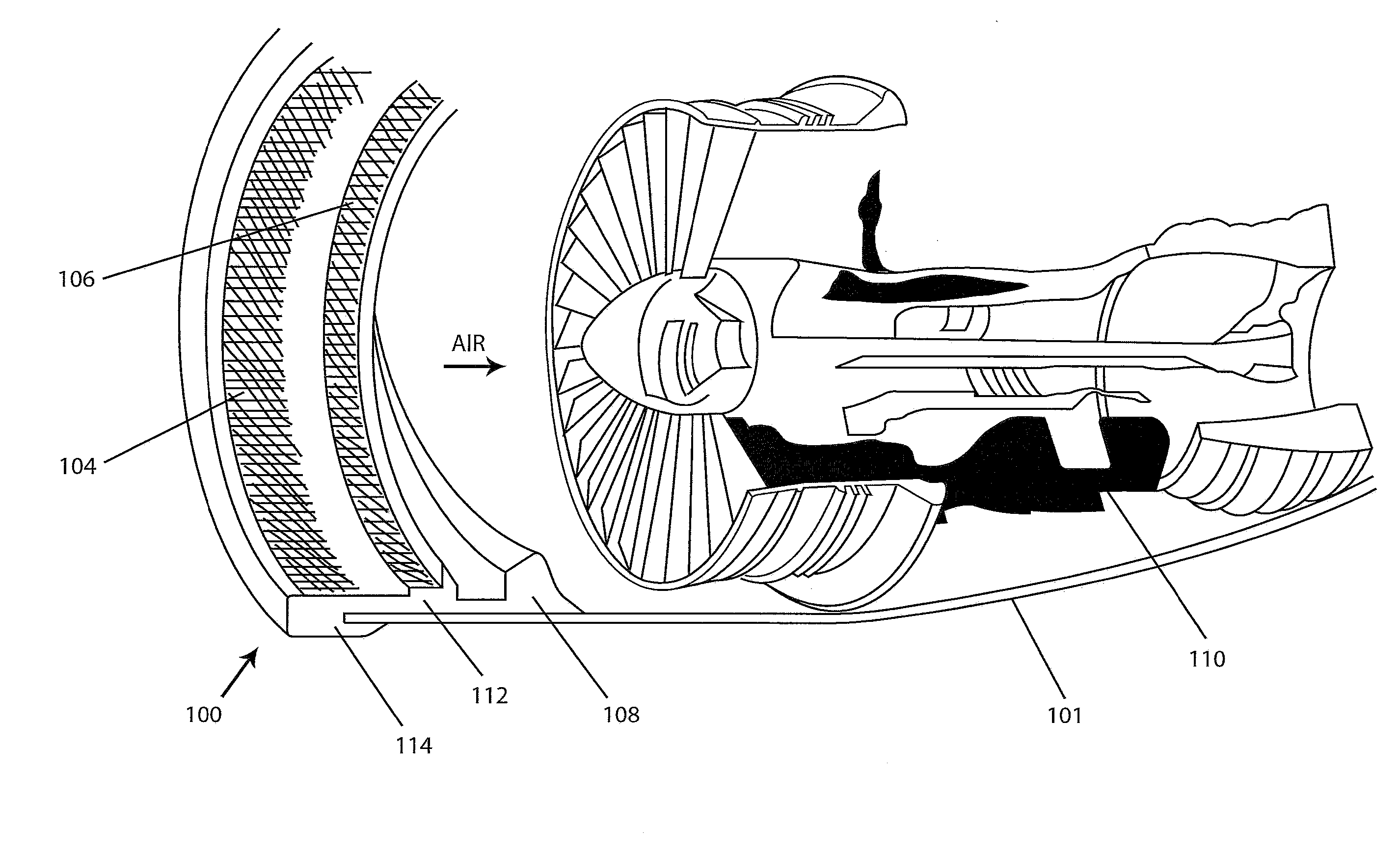
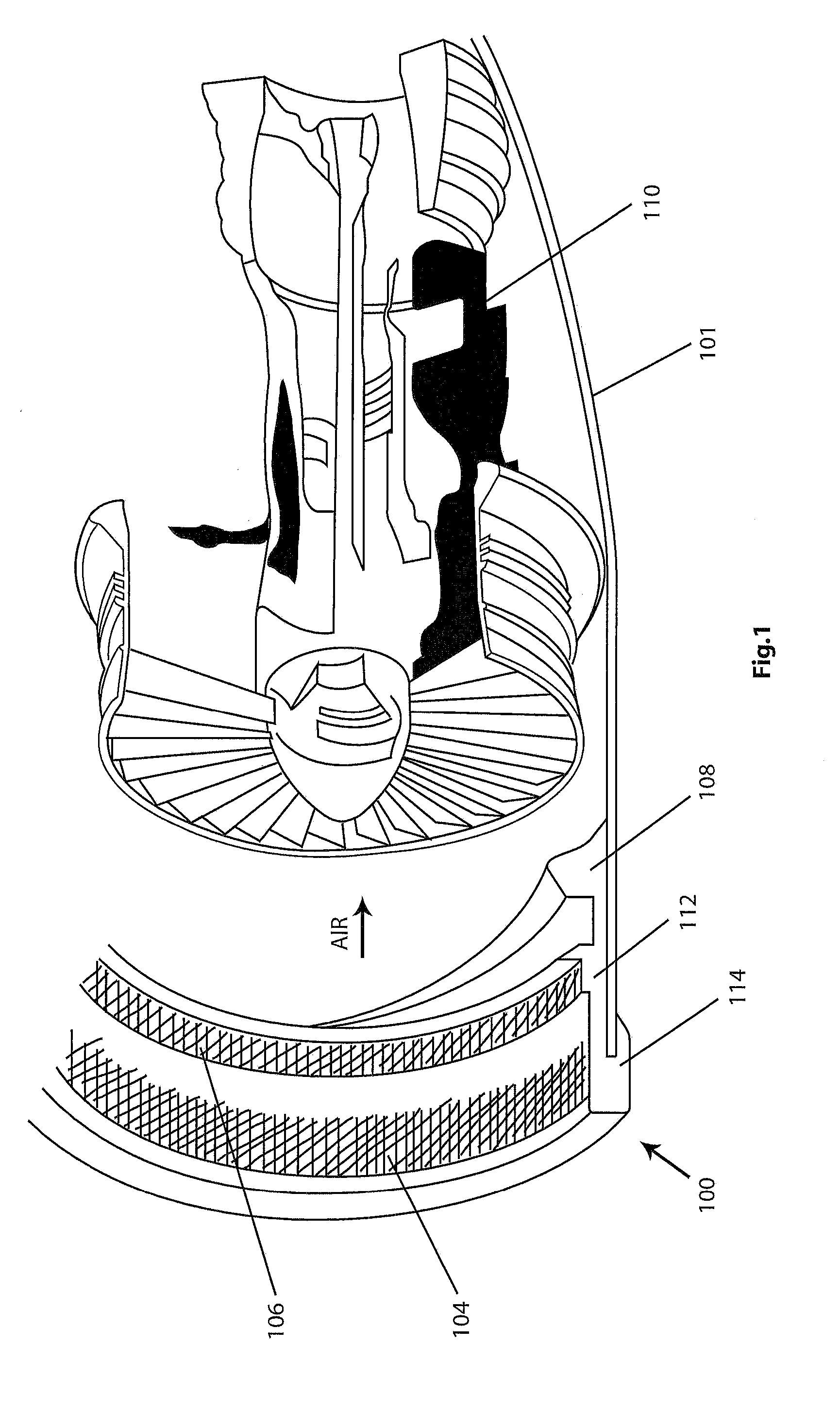
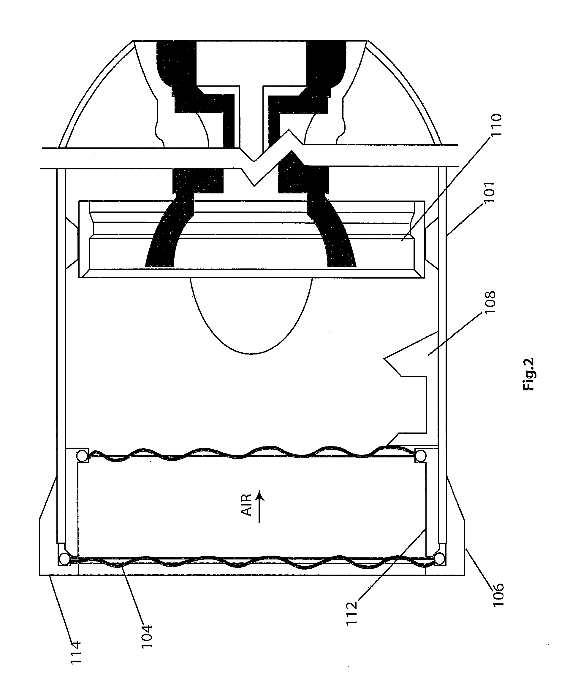
[0021]FIGS. 1 and 2 show a partially broken and a cross sectional view, respectively, of a jet engine equipped with an embodiment of an engine protection device according to the present invention. In FIGS. 1 and 2 the engine protection device (100), is depicted as being fitted to an aircraft engine nacelle 101. The nacelle is a cover housing (separate from the fuselage) that holds the engine on an aircraft. The engine protection device has a first deflection web (104), a second deflection web (106) and capture basket device (108). The capture or arc basket 108 is fitted inside the engine nacelle (101) and rests upon the interior surface of the nacelle at a position in front of the engine turbine (110). The capture basket 108 has a curved profile (shown in FIG. 1), which extends along a portion of the circumference of the nacelle. The capture basket (108) has a high wall (206) and a low wall (204) (FIGS. 2 and 3) that cooperate to retain foreign bodies not deflected by the first and ...


PUM


Abstract

A jet engine intake guard includes an engine sleeve located within the nacelle of the engine; a primary deflection screen located at a front portion of the sleeve and having a first circular frame formed of a tubular fabric member and a plurality of fiber yarn strings disposed across the diameter of the primary frame and attached to one another in a tri-axle weave pattern. The guard also includes a secondary deflection screen located behind the primary deflection screen in the direction of air flow through the engine and having a second circular frame formed of a tubular fabric member and a plurality of fiber yarn strings disposed across the secondary frame and attached to one another in a tri-axle weave pattern. The guard further includes a capture basket located between the primary and secondary deflection screens. The capture basket has a first wall located toward the primary deflection screen, a center portion and a second wall located toward the secondary deflection screen. In a preferred embodiment the entire guard is made of woven carbon fiber.

Description

RELATED APPLICATION DATA[0001]This application claims priority to provision application No. 61 / 271,496, filed on Jul. 22, 2009.BACKGROUND OF THE INVENTION[0002]This invention relates to aircraft engine protection devices and, more particularly, to covers placed in front of the fan blades of aircraft engines so as to prevent the intrusion of foreign bodies. The present invention is directed to a device designed to prevent the intake of both large animals and foreign objects into the aircraft.[0003]Protecting airplanes from damage due to birds or other airborne hazards has long been the goal of the prior art. While a direct strike on a fuselage is damaging to the airframe, the more pressing issue is when a bird strikes or other airborne hazard strikes the internal machinery of the engine assembly. Bird or foreign body strikes can cause catastrophic engine failure, resulting in loss of control of the airplane and possibly a forced or emergency landing. Currently, there is no effective ...

Claims


Application Information

Patent Timeline
IPC IPC(8): F02G3/00
CPCB64D2033/022B64D33/02Y10T137/0536
Inventor SILVA, BROOKSAVERY, DONNA
Owner THE CTFOT GROUP
Why Eureka
Try Eureka