Semiconductor test equipment with concentric pogo towers

a technology of semiconductor test equipment and concentric pogo towers, which is applied in the direction of electrical testing, measurement devices, instruments, etc., can solve the problems of obsolete equipment, signal types getting more complex related, and almost inability to change the specifics of semiconductor test equipment, so as to prevent miss-assembling, easy to disassemble, expand, or maintain

Active Publication Date: 2011-01-27
KING YUAN ELECTRONICS
View PDF5 Cites 3 Cited by
  • Summary
  • Abstract
  • Description
  • Claims
  • Application Information

AI Technical Summary

Benefits of technology

[0008]According to the present invention, the inner pogo tower integrates with the outer pogo tower through the second connecting component correspondingly engaging with the first connecting component. Moreover, the outer pogo tower is fixed to the load board of the tester head together with the inner pogo tower corresponding to the recessed card holder of the base. In which, the plurality of inner pogo pins and the plurality of outer pogo pins are electrically connected to the load board respectively. Therefore, the present invention due to the integration of the inner pogo tower and the outer pogo tower, which through the second connecting component correspondingly engaging with the first connecting component, it is capable of expanding the test specifications.
[0009]Preferably, the first connecting component of the outer pogo tower is detachably engaged with the second connecting component of the inner pogo tower, so that the present invention can easily to disassemble, expand, or maintain based on the process requirements. Alternatively, the outer pogo tower may undetachably engage to the inner pogo tower. Furthermore, the second connecting component includes at least one connecting slot recessed on the outer peripheral surface. The at least one connecting slot may comprises an opened end and a closed end, wherein the opened end is configured faraway from the load board rather than the closed end.
[0010]In addition, the first connecting component of the outer pogo tower may include at least one connecting pin radially protruded from the inner annular surface of the outer pogo tower. The at least one connecting pin correspondingly sliding into the opened end of the at least one connecting slot and stopped at the closed end for engagement. Hence, the at least one connecting slot of the second connecting component of the inner pogo tower lodges in the at least one connecting pin of the first connecting component to be received in the outer pogo tower, in order to disassemble and assemble easily. Besides, as well as the aforementioned first and second connecting component can be exchanged, or utilize the way of embedding, lodging, fastening, locking, or other equivalents.
[0011]Further, the at least one connecting slot of the inner pogo tower may comprises two or more axially extended slots, L-shaped slot, spiral slot, or any other form of slot. In addition, the at least one connecting pin of the outer pogo tower may comprises two or more springy pins which be preferably set at unequal angle to prevent miss-assembling. Among which, the inner annular surface of the outer pogo tower provides at least one pin receiving hole, at least one of the springy pins comprises a spring and a short pin received in the at least one pin receiving hole, the short pin comprises one end pushed against the spring, and an opposite end exposed outside the inner annular surface. Thus, the short pin of the springy pin is capable of retractility and reposition, and to provide an effectiveness of radial retractable positioning.

Problems solved by technology

In terms of the current technology, the specifications of semiconductor test equipments almost cannot be changed.
However, due to the development of the functional integration are higher and higher in electronic products, the signal types are getting more complex related thereof.
For this purpose, the outdated equipment with the 256 input / output channels and 16 groups DPS is difficult to further expand its test specifications due to limitations of original software or hardware, expect for re-purchasing new equipment with the 512 input / output channels and 32 groups DPS.
Although the re-equipped equipments are existed in order to expand the test specifications, it takes considerable costs of re-equipping and would not be compatible with the original test specifications after re-equipped.

Method used


Image

  • Semiconductor test equipment with concentric pogo towers
  • Semiconductor test equipment with concentric pogo towers
  • Semiconductor test equipment with concentric pogo towers

Examples


Embodiment Construction

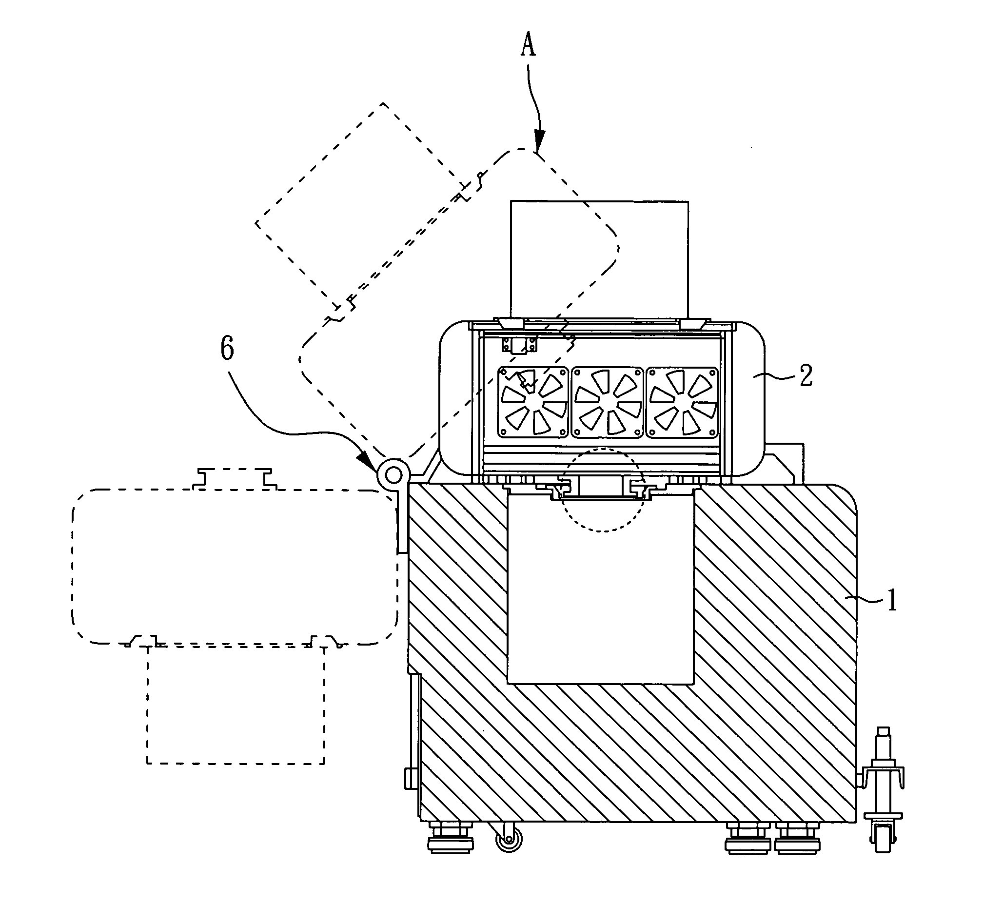
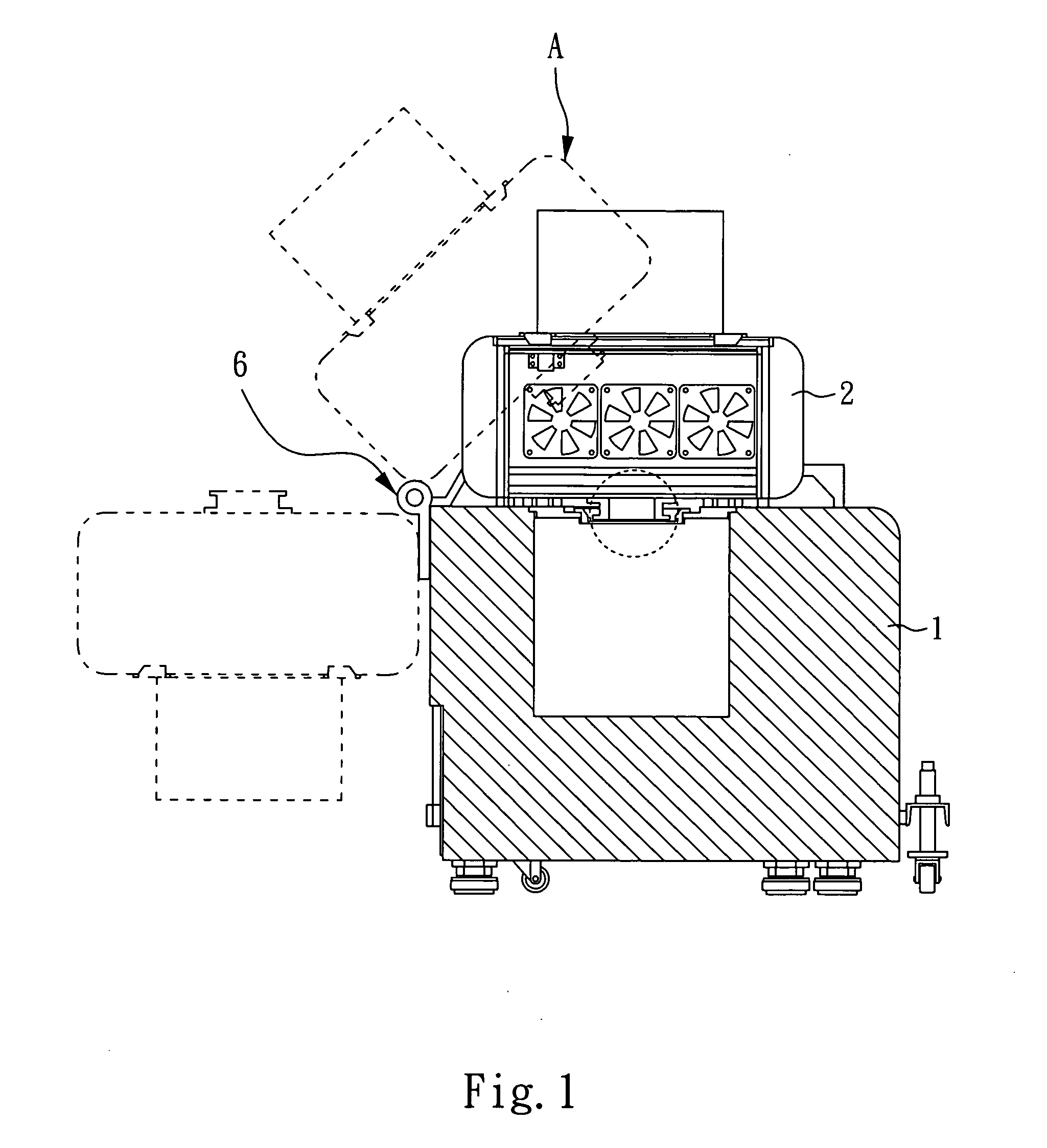
[0021]Please referring to FIG. 1 together with FIG. 2, FIG. 1 is a schematic diagram showing a semiconductor test equipment as a whole according to a first preferred embodiment of the present invention; and FIG. 2 is a perspective view showing a tester head, being located in position a, according to a first preferred embodiment of the invention. As shown in the figures, a base 1 includes a stage 11 thereon, and a recessed card holder 111 is provided on the stage 11 which is used to place a probe card 5, a small size probe card 50, a wafer to be tested, or other semiconductor chips or electronic components to be tested. In addition, the figures show a tester head 2 which may rotate closer to or away from the stage 11 of the base 1 through a rotating arm 6. The tester head 2 is separably disposed on the stage 11 of the base 1, a load board 21 that comprises circuits and contacts is provided below the tester head 2.

[0022]Further referring to FIG. 3, FIG. 3 is an exploded view diagram s...


PUM


Abstract

A semiconductor test equipment with concentric pogo towers is disclosed, which comprises a base, a tester head, an outer pogo tower, and an inner pogo tower. The inner pogo tower is concentrically received in the outer pogo tower, and a connecting slot of the inner pogo tower is correspondingly engaged with a connecting pin of the outer pogo tower. The outer pogo tower is fixed to the load board together with the inner pogo tower, whereby a plurality of outer pogo pins of the outer pogo tower and a plurality of inner pogo pins of the inner pogo tower are electrically connected to the load board respectively. Therefore, the present invention is capable of expanding the test specifications, but also to change rapidly from different test specifications through replacing a different probe card but without to modify any other hardware.

Description

BACKGROUND OF THE INVENTION[0001]1. Field of the Invention[0002]The present invention relates to a semiconductor test equipment with concentric pogo towers, and more particularly, to a semiconductor test equipment with expandable pogo tower.[0003]2. Description of Related Art[0004]In terms of the current technology, the specifications of semiconductor test equipments almost cannot be changed. For instance, the conventional specifications of common semiconductor test equipment have 256 input / output channels and 16 groups DPS. However, due to the development of the functional integration are higher and higher in electronic products, the signal types are getting more complex related thereof.[0005]However, improving the testing capacity in order to satisfy the current industrial requirements, the testing capabilities have been improved continuously. Hence, the specifications have been gradually upgraded from the 256 input / output channels and 16 groups DPS to the 512 input / output channel...

Claims


Application Information

Patent Timeline
Patent Type & Authority Applications(United States)
IPC IPC(8): G01R31/02G01R31/26
CPCG01R31/2889
Inventor CHEN, FONG JAY
Owner KING YUAN ELECTRONICS
Why Eureka
Try Eureka