Permanent magnet and method for manufacturing the same

Inactive Publication Date: 2011-01-27
NITTO DENKO CORP
View PDF11 Cites 12 Cited by
  • Summary
  • Abstract
  • Description
  • Claims
  • Application Information

AI Technical Summary

Benefits of technology

[0017]According to the permanent magnet having the constitution of the above (1), the permanent magnet is constituted by the magnet obtained by wet-mixing the Dy compound or the Tb compound with the magnet raw material to coat the surface of the magnet raw material with the Dy compound or the Tb compound, and sintering the green sheet obtained by mixing the resulting magnet raw material with the resin binder and molding the resulting mixture. Accordingly, it becomes possible to sufficiently improve the coercive force by Dy or Tb while decreasing the amount of Dy or Tb used. Further, it can be prevented that Dy or Tb is solid-solutionized in the magnet particles to decrease the residual magnetization.
[0018]Further, according to the permanent magnet of the above (2), the Dy compound or the Tb compound is unevenly distributed in the grain boundary of the magnet raw material after sintering, so that it becomes possible to sufficiently improve the residual magnetization and coercive force by Dy or Tb while decreasing the amount of Dy or Tb used.
[0019]Furthermore, according to the permanent magnet of the above (3), the content of the above-mentioned Dy compound or Tb compound is from 0.01 to 8 wt %, so that it becomes possibl

Problems solved by technology

However, Dy is a rare metal, and the locality thereof is limited, so that it i

Method used


Image

  • Permanent magnet and method for manufacturing the same
  • Permanent magnet and method for manufacturing the same
  • Permanent magnet and method for manufacturing the same

Examples


Example

[0028]1: Permanent magnet[0029]41: Slurry[0030]42: Green sheet

BEST MODE FOR CARRYING OUT THE INVENTION

[0031]A specific embodiment of a permanent magnet and a method for manufacturing the permanent magnet according to the invention will be described below in detail with reference to the drawings.

[0032]Constitution of Permanent Magnet

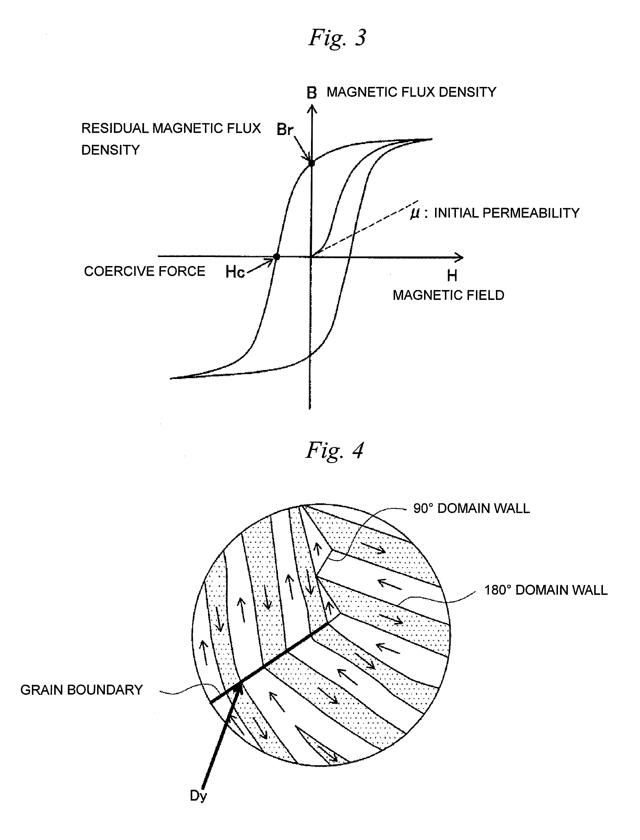
[0033]First, a constitution of a permanent magnet 1 will be described using FIGS. 1 to 4. Incidentally, in this embodiment, particularly, an explanation is given taking the permanent magnet 1 buried in a VCM as an example.

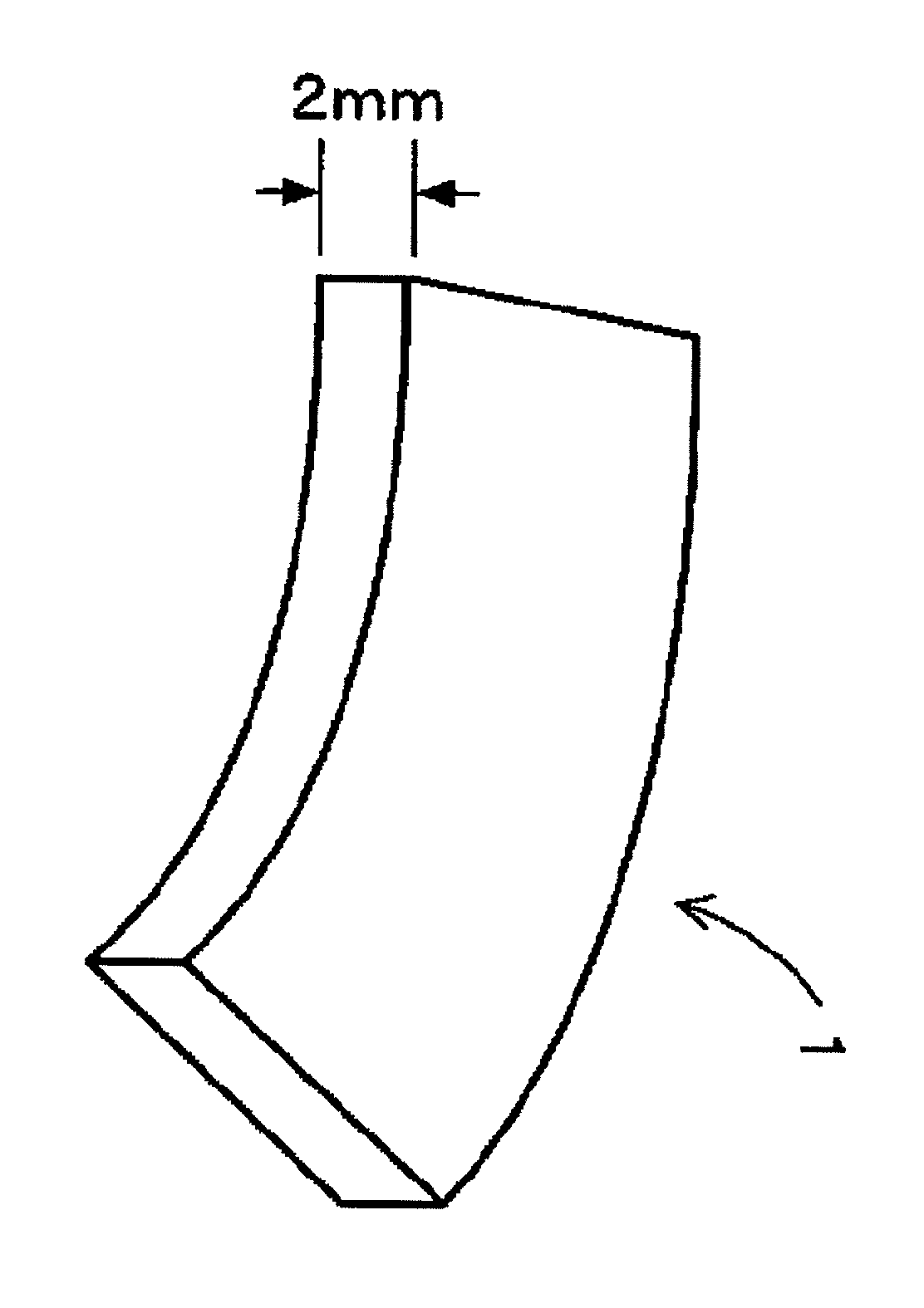
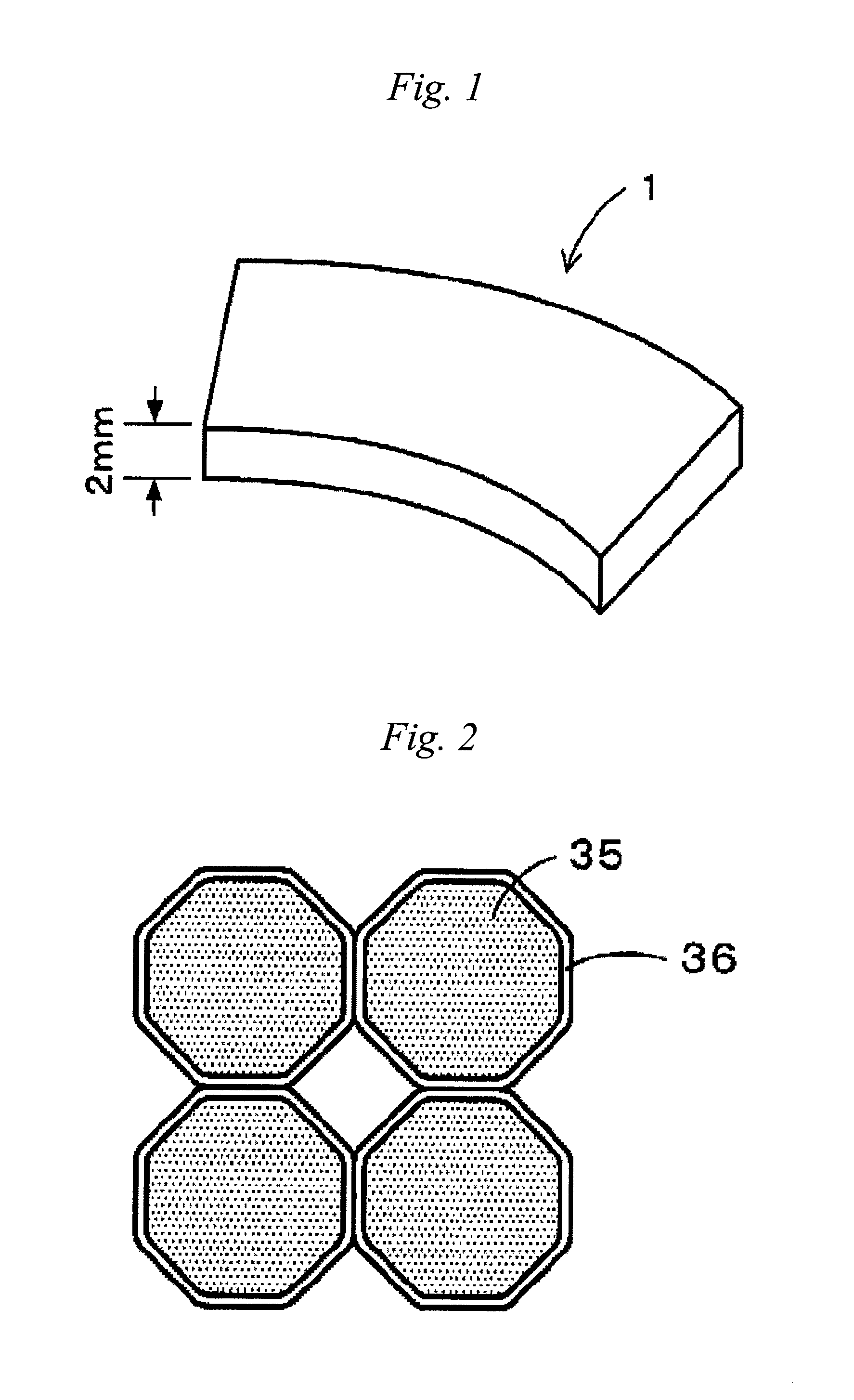
[0034]The permanent magnet 1 according to this embodiment is a Nd—Fe—B-based magnet. Further, Dy (dysprosium) for increasing the coercive force of the permanent magnet 1 is added. Incidentally, the contents of respective components are regarded as Nd: 27 to 30 wt %, Dy (or Tb): 0.01 to 8 wt %, B: 1 to 2 wt %, and Fe (electrolytic iron): 60 to 70 wt %. Furthermore, the permanent magnet 1 is constituted from a fan-shaped and thin film-like...


PUM

PropertyMeasurementUnit
Grain boundaryaaaaaaaaaa

Abstract

The present invention relates to a permanent magnet obtained by wet-mixing a Dy compound or a Tb compound with a magnet raw material to coat a surface of the magnet raw material with the Dy compound or the Tb compound, and sintering a green sheet obtained by mixing the resulting magnet raw material with a resin binder and molding the resulting mixture. Since the present invention has the above-mentioned constitution, it becomes possible to sufficiently improve coercive force by Dy or Tb while decreasing the amount of Dy or Tb used. Further, it can be prevented that Dy or Tb is solid-solutionized in magnet particles to decrease residual magnetization.

Description

TECHNICAL FIELD[0001]The present invention relates to a permanent magnet and a method for manufacturing the permanent magnet.BACKGROUND ART[0002]In recent years, a reduction in size and weight, an increase in power and an increase in efficiency have been required for permanent magnetic motors used in hybrid cars, hard disk drives or the like. In particular, with recent requirement for a reduction in size of the hard disk drives, a further reduction in size and thickness has been required for voice coil motors (hereinafter referred to as VCMs) used for head driving of the hard disk drives as shown in patent document 1.[0003]Then, in realizing the reduction in size and thickness in the above-mentioned VCMs, a reduction in film thickness and further improvement in magnetic characteristics have been required for permanent magnets buried in the VCMs. Incidentally, as the permanent magnets, there are ferrite magnets, Sm—Co-based magnets, Nd—Fe—B-based magnets, Sm2Fe17Nx-based magnets and ...

Claims


Application Information

Patent Timeline
IPC IPC(8): H01F7/02B29C71/02
CPCH01F1/0552H01F1/0557H01F1/0572H01F41/0293H01F41/0266H01F41/16H01F1/0577
Inventor OZEKI, IZUMIKUME, KATSUYANAKAYAMA, JUNICHIFUKUDA, YUUKIHOSHINO, TOSHINOBUHORIO, TOMOKAZU
Owner NITTO DENKO CORP
Why Eureka
Try Eureka