Electronic display mounting system

Active Publication Date: 2011-01-27
DAKTRONICS
View PDF62 Cites 77 Cited by
  • Summary
  • Abstract
  • Description
  • Claims
  • Application Information

AI Technical Summary

Benefits of technology

[0018]Still another significant aspect and feature of the present invention is the use of common geometry slotted frame components including a slotted frame top, a slotted frame bottom, and slotted frame ends which form connected inner panels where the slotted frame top and the slotted frame bottom serve as mounts for vertically aligned formed channels including formed mid-channels. The perimeter of the slotted frame components and the formed vertically aligned channels are not welded but are riveted in prepunched holes in order to automate

Problems solved by technology

Welding is very time consuming and is a hard process to control with respect to uniformity and trueness of surfaces.
Welding also reduces the strength characteristics of aluminum structures used therein and th

Method used


Image

  • Electronic display mounting system
  • Electronic display mounting system
  • Electronic display mounting system

Examples


Embodiment Construction

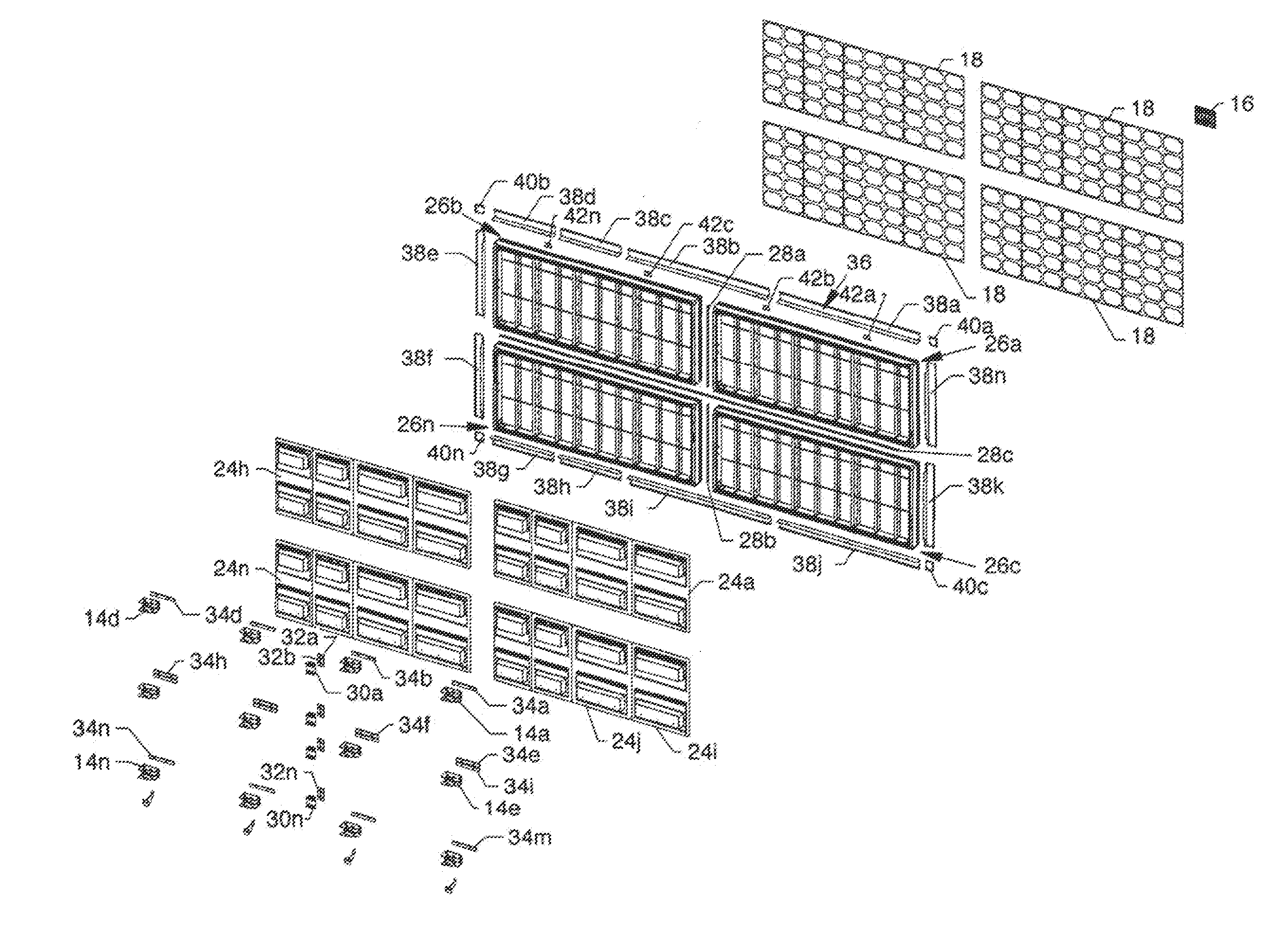
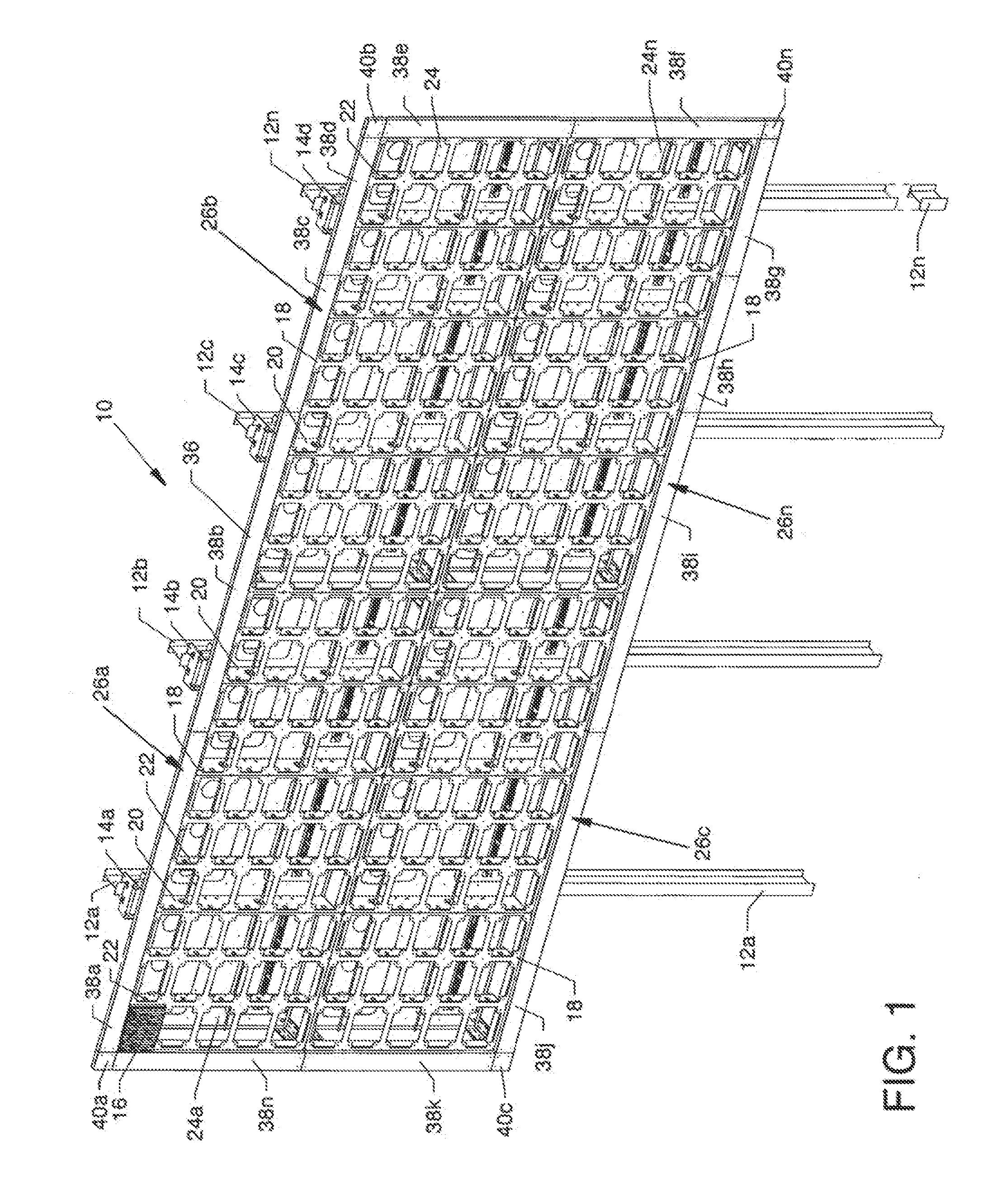
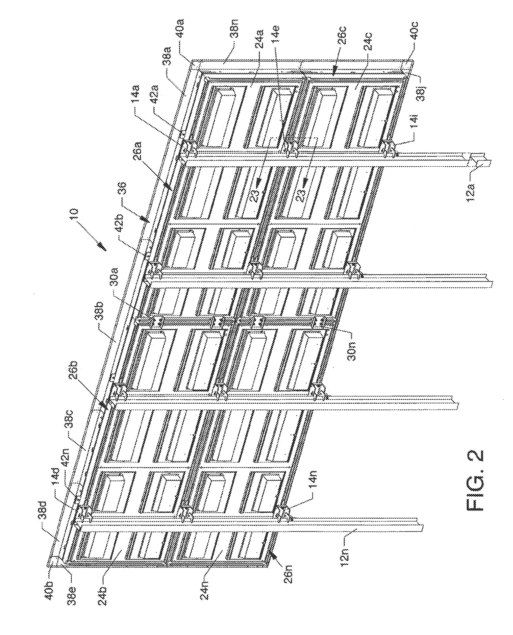
[0054]FIG. 1 is an isometric front view of an electronic sign having slotted frame cabinets 10, the present invention, mounted to a plurality of support structures 12a-12n by a plurality of like mounting clamps 14a-14n being part of and being located along and about the rear of the invention, as also shown in FIG. 2. One of a plurality of like electronic display modules 16 (also known as LED modules) having a four-point latching system populate the front of the present invention and are removably attached to a plurality of mounting panels 18 extending along and about the front of the invention. The structure and relationship of the mounting panels 18 and the electronic display modules 16 are described in U.S. Pat. No. 7,055,271 entitled “Electronic Display Module Having a Four-Point Latching System for Incorporation into an Electronic Sign and Process” and is incorporated herein in its entirety.

[0055]Also visible is a plurality of vertically aligned formed channels 20 of full width ...


PUM


Abstract

An electronic sign having slotted frame cabinets whereby each slotted frame cabinet can conveniently be attached to one or more vertically or horizontally positioned adjacent slotted frame cabinets by using connecting components which are generally located around the periphery of one or more slotted frame cabinets. Connecting components, including splice bars, splice plates, and mounting clamps, are aligned in, positioned along and secured to backing bars which are co-located in backing bar slots in one or more of the slotted frame cabinets. Lift eyes can be variably located in one or more lift eye slots. The use of externally located connecting components, which do not extend through the cabinetry, minimize the entry of environmental elements into the interior of the electronic sign. Multiple slotted frame cabinets can be connected without the removal of LED display panels.

Description

CROSS REFERENCES TO RELATED APPLICATIONS[0001]This patent application is related to patent application Ser. No. 11 / 809,107 filed on May 31, 2007, now issued as U.S. Pat. No. 7,694,444, entitled “Electronic Sign Having a Formed Metal Cabinet.”[0002]This application is also related to patent application Ser. No. 10 / 688,304 filed on Oct. 17, 2003, now issued as U.S. Pat. No. 7,055,271, entitled “Electronic Display Module Having a Four-Point Latching System for Incorporation into an Electronic Sign and Process.”[0003]This application is a divisional of and claims the benefit of priority under 35 U.S.C. §120 to U.S. patent application Ser. No. 12 / 077,130, filed on Mar. 17, 2008, which claims the benefit of priority under 35 U.S.C. §119(e) to the earlier filed U.S. Provisional Application No. 60 / 923,366 filed Apr. 13, 2007, entitled “Cabinet Having Perimeter Track,” the benefit of priority of each of which is claimed hereby, and each of which are incorporated into this application by refe...

Claims


Application Information

Patent Timeline
IPC IPC(8): H05K7/00F16B2/02F16M13/02
CPCF16B2/12F16B7/0473H04N5/64H05K5/06H05K5/0017H05K5/0021H05K5/0204G09F9/3026
Inventor KLUDT, KORY D.NEYENS, RUSSELL J.MAMMENGA, JON M.
Owner DAKTRONICS
Why Eureka
Try Eureka