
Speaker

Inactive Publication Date: 2011-01-27
PANASONIC CORP
View PDF9 Cites 2 Cited by
  • Summary
  • Abstract
  • Description
  • Claims
  • Application Information

AI Technical Summary

Benefits of technology

[0013]This structure improves a phase difference within the diaphragm and provides the loudspeaker with high sound quality.

Problems solved by technology

The deeper is the cone diaphragm, the larger becomes the harmful influence, therefore deteriorating sound quality even if having preferable frequency characteristics.
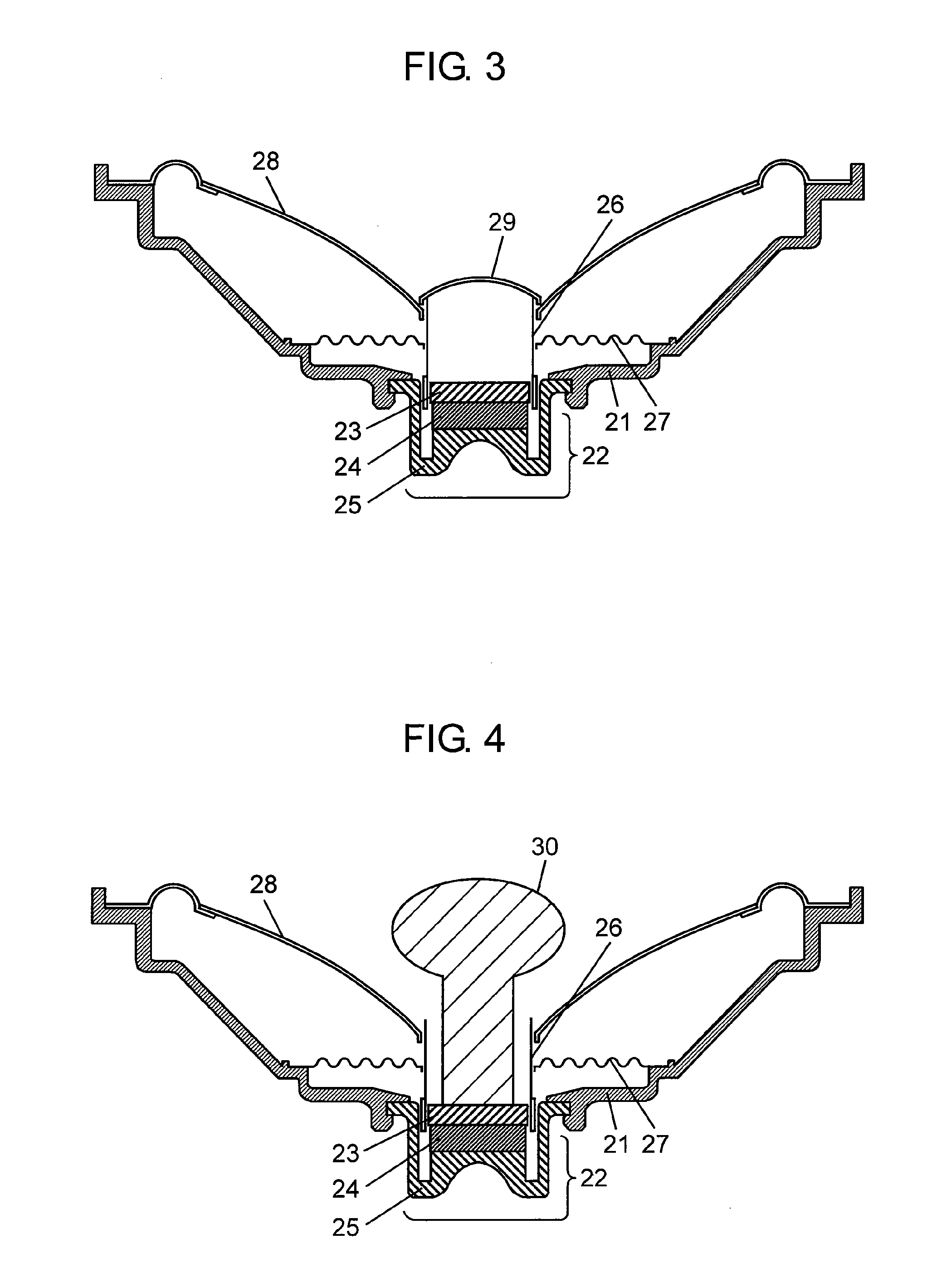
Example 3 of loudspeaker causes reflection and diffraction, however, a concave space inside sub-cone 31 disturbs the phases, not improving the phase against the vibrating surface.
However, a sound generated by dust cap 42 and a sound generated by the sub-cone paper cause a phase interference with a difference in a distance between the dust cap and the cone paper, causing a large dip of a sound pressure at a certain frequency, still providing a problem.

Method used


Image

  • Speaker
  • Speaker
  • Speaker

Examples


exemplary embodiment 1

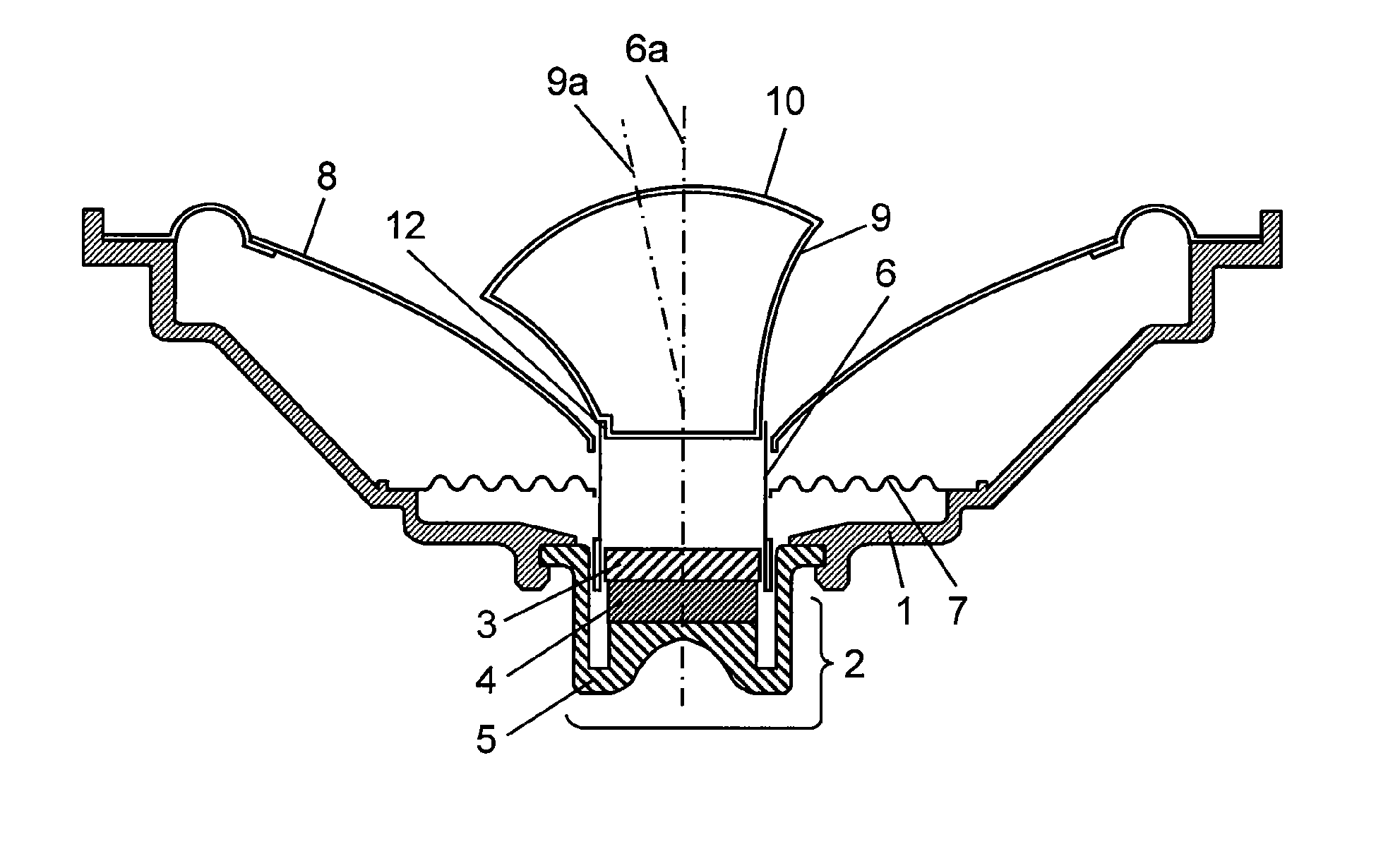
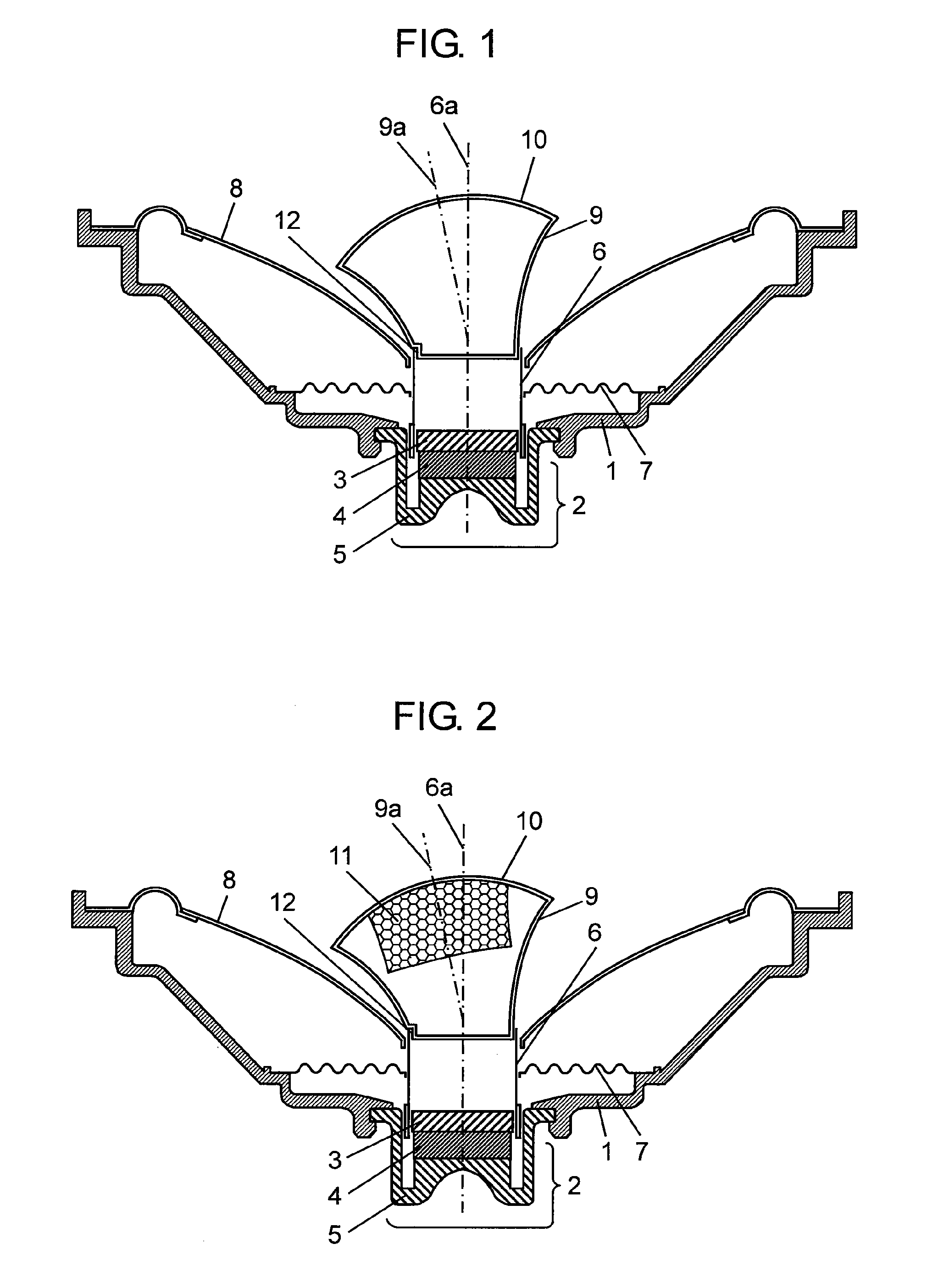
[0035]FIG. 1 is a cross-sectional view of a loudspeaker in accordance with Exemplary Embodiment 1 of the present invention. The construction of the loudspeaker according to Embodiment 1 will be explained first with FIG. 1. As shown in FIG. 1, magnet 4 is bonded to yoke 5. Top plate 3 is bonded onto an upper surface of magnet 4. Yoke 5, magnet 4, and top plate 3 which are bonded to each other constitute magnetic circuit 2 having a magnetic gap having an annular shape. Magnetic circuit 2 is coupled to a lower surface of frame 1 made of resin. An outer periphery of cone diaphragm 8 is bonded to a periphery of frame 1. Voice coil 6 is coupled to the center of cone diaphragm 8 and placed in the magnetic gap formed in magnetic circuit 2. Damper 7 is bonded to voice coil 6 for supporting voice coil 6.

[0036]The loudspeaker according to Embodiment 1 has the following features. The loudspeaker according to Embodiment 1 includes frame 1 coupled to magnetic circuit 2, cone diaphragm 8 coupled t...

exemplary embodiment 2

[0043]FIG. 2 is a cross-sectional view of a loudspeaker in accordance with Exemplary Embodiment 2 of the invention. In FIG. 2, components identical to whose of conventional example 1 shown in FIG. 3 are denoted by the same reference numerals, and their description will be omitted. A difference of the loudspeaker according to Embodiment 2 from the loudspeaker according to Embodiment 1 is that sound absorber 11 is placed in a space surrounded by tubular port 9 and dome 10. The sound absorber absorbs a resonance sound generated by tubular port 9, dome 10, and the internal space surrounded by the port and dome as to adjust sound quality.

[0044]As shown in FIG. 2, sound absorber 11 is made of porous material. The absorber is fixed to dome 10, but may be fixed to tubular port 9 when necessary, or may fill the whole internal space. The sound absorber may be made of fibrous material instead of the porous material.

exemplary embodiment 3

[0045]A difference of a loud speaker according to Embodiment 3 from the loudspeakers according to Embodiment 1 and 2 is that a total mass of dome 10, tubular port 9, and a portion surrounded by the port and dome is close to an effective mass of cone diaphragm 8. This structure balances a mass of an inner part of voice coil 6 with a mass of an outer part of the voice coil, and allows piston motion of the voice coil in a wider frequency range, thereby improving sound quality. According to experiments, the difference between the total mass and the effective mass was preferably smaller than 40% as to improve sound quality.


PUM


Abstract

A loudspeaker includes a frame coupled to a magnetic circuit, a cone diaphragm coupled to an outer periphery of the frame, a voice coil coupled to the cone diaphragm, the voice coil having a portion placed in a magnetic gap of the magnetic circuit, a tubular port having an end coupled to the voice coil, and a diameter of another end of the tubular port is larger than a diameter of a connecting portion at which the end of the tubular port is coupled to the voice coil, and a dome covering an upper end of the tubular port. A center axis of the tubular port inclines at least by 5° with respect to a center axis of the voice coil.

Description

TECHNICAL FIELD[0001]The invention relates to a loudspeaker to be used for various acoustic devices, particularly to a loudspeaker having an improved performance and sound quality.BACKGROUND ART[0002]FIG. 3 is a cross-sectional view of conventional example 1 of loudspeaker. This loudspeaker has a typical conventional structure, i.e., a single cone loudspeaker. As shown in FIG. 3, magnet 24 is bonded to yoke 25. Top plate 23 is bonded onto an upper surface of magnet 24. Yoke 25, magnet 24 and top plate 23 which are bonded to each other constitute magnetic circuit 22 having a magnetic gap having a cylindrical shape.[0003]Magnetic circuit 22 is bonded to a lower surface of frame 21 made of resin. An outer periphery of cone diaphragm 28 is bonded to an outer periphery of frame 21. Voice coil 26 is bonded to a center part of cone diaphragm 28, and is placed in the magnetic gap formed in magnetic circuit 22. Damper 27 is bonded as to support voice coil 26. Dust cap 29 serving as a dustpro...

Claims


Application Information

Patent Timeline
IPC IPC(8): H04R9/06
CPCH04R1/345H04R7/12H04R2499/13H04R9/06H04R9/02
Inventor YAMAGISHI, KIYOSHI
Owner PANASONIC CORP
Learn More