Swash plate type compressor
- Summary
- Abstract
- Description
- Claims
- Application Information
AI Technical Summary
Benefits of technology
Problems solved by technology
Method used
Image
Examples
first embodiment
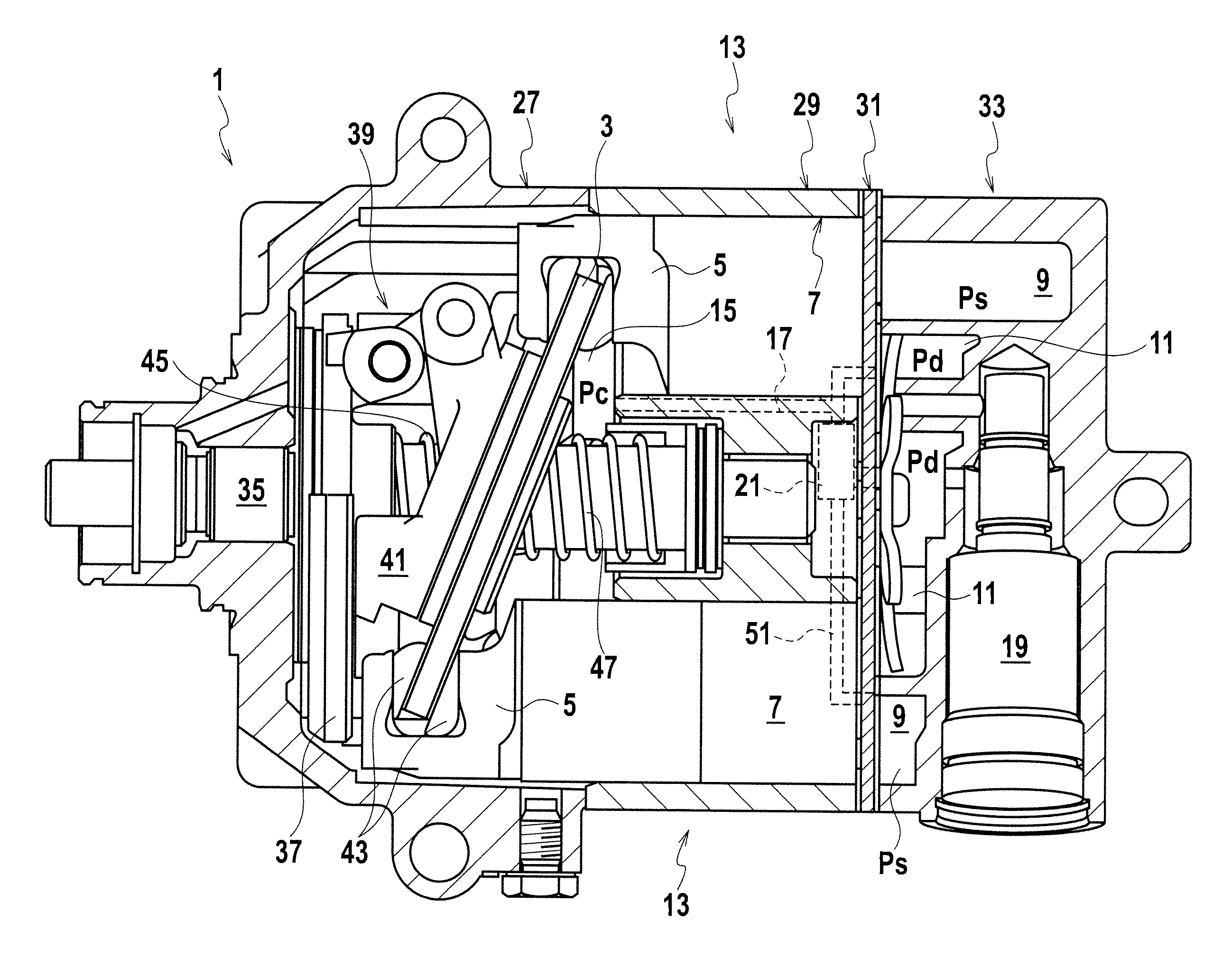
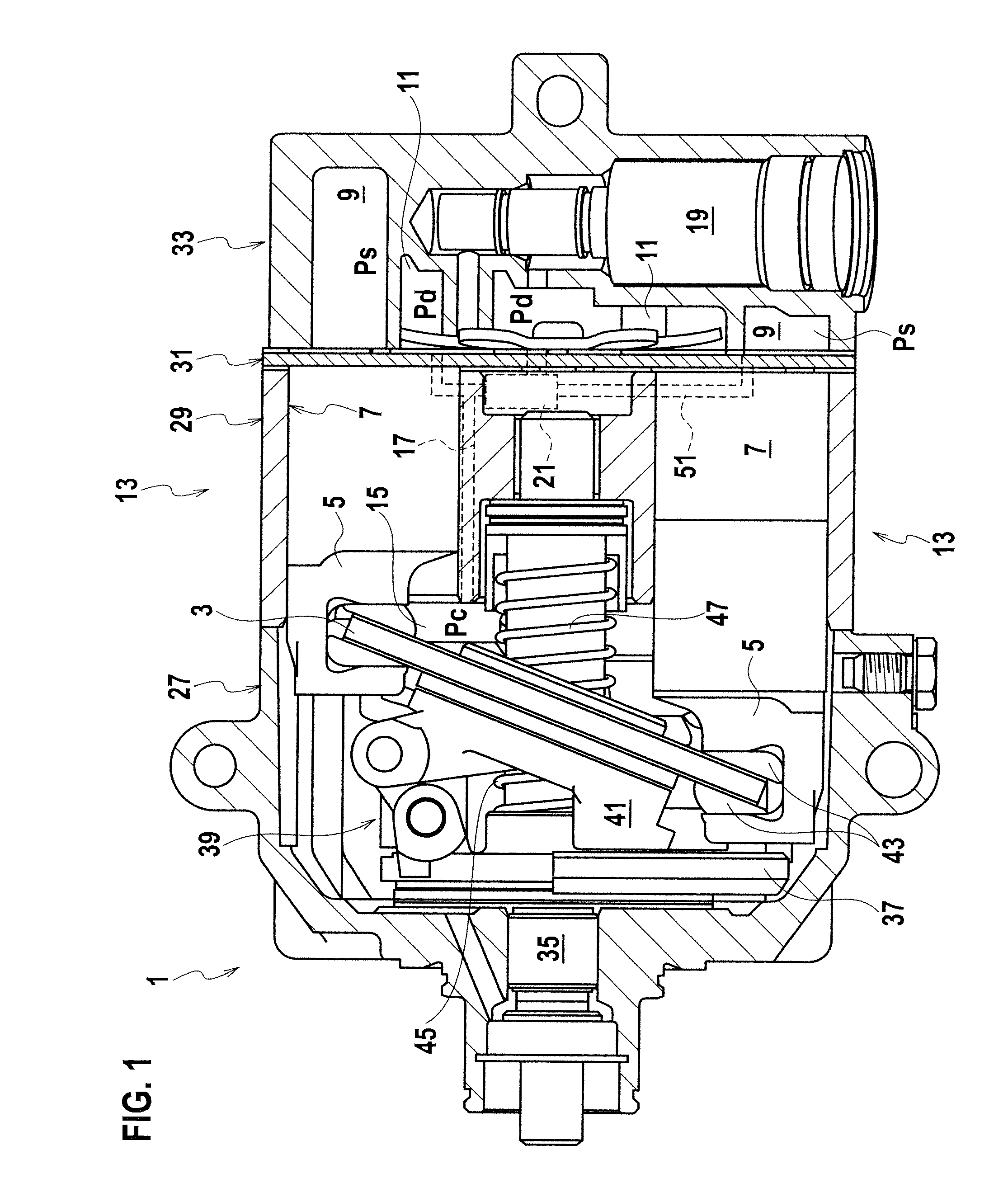
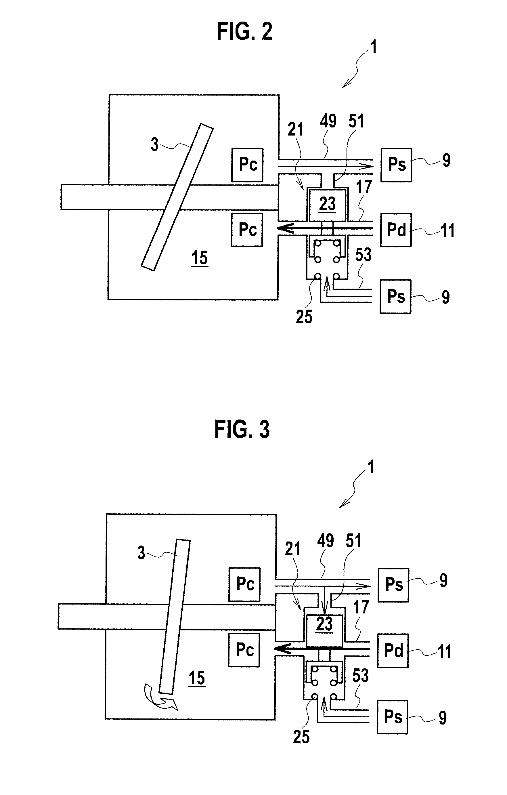
[0030]A swash plate type compressor 1 in a first embodiment will be explained with reference to FIG. 1 to FIG. 3.
[0031]As shown in FIG. 1, the swash plate type compressor 1 includes a swash plate 3, compression mechanisms 13, a crank chamber 15 and a capacity control valve 19. The swash plate 3 has pistons 5 and cylinders 7. The compression mechanisms 13 are driven by an inclined rotation of the swash plate 3 to compress refrigerant (gas) suctioned from a suction chamber 9 and then discharge it to a discharge chamber 11. By the crank chamber 15, a crank pressure Pc is applied to the swash plate 3 and heads of the pistons 5. By the capacity control valve 19, the refrigerant in the suction chamber 11 is introduces into the crank chamber 15 through an introduction flow passage 17 and a swash angle of the swash plate 3 is adjusted. Further, a differential pressure control valve 21 is provided. The differential pressure control valve 21 acts due to a differential pressure (Pc−Ps) between...
second embodiment
[0046]A swash plate type compressor 101 in a second embodiment will be explained with reference to FIG. 4. Hereinafter, different points from the swash plate type compressor 1 in the first embodiment will be explained.
[0047]In the swash plate type compressor 101, the introduction flow passage 17 is closed by the differential pressure control valve 21 and an open criterion value of the differential pressure control valve 21 is set to 0.7 MPa. When the differential pressure (Pc−Ps) between the crank pressure Pc and the suction pressure Ps exceeds 0.7 MPa, the slide valve 23 moves to the close position of the introduction flow passage 17 against the urging force of the coil spring 25. When the differential pressure (Pc−Ps) becomes equal-to or less-than 0.7 MPa, the slide valve 23 is moved back to the open position of the introduction flow passage 17 by the urging force of the coil spring 25.
[0048]Generally, if the refrigerant is not sent to the crank chamber 15 due to the full-close of...
third embodiment
[0051]A swash plate type compressor 201 in a third embodiment will be explained with reference to FIG. 5. Hereinafter, different points from the swash plate type compressor 1 in the first embodiment will be explained.
[0052]In the swash plate type compressor 201, provided is a stopper 203 that restrains the slide valve 23 of the differential pressure control valve 21 in the close position. In a state where the position of the slide valve 23 is restrained by the stopper 203, a bypass passage 205 (an appropriate gap) is formed between the slide valve 23 and the introduction flow passage 17.
[0053]Accordingly, if the differential pressure control valve 21 rises, the slide valve 23 never close off the introduction flow passage 17 completely and a given amount of the refrigerant is sent to the crank chamber 15. Therefore, ensured is a function to reduce each discharge amount of the compression mechanisms 13 to its minimum value.
[0054]Note that, in this case, an amount of the refrigerant se...
PUM
 Abstract
Description
Claims
Application Information
 - R&D
- Intellectual Property
- Life Sciences
- Materials
- Tech Scout
- Unparalleled Data Quality
- Higher Quality Content
- 60% Fewer Hallucinations
Browse by: Latest US Patents, China's latest patents, Technical Efficacy Thesaurus, Application Domain, Technology Topic, Popular Technical Reports.
© 2025 PatSnap. All rights reserved.Legal|Privacy policy|Modern Slavery Act Transparency Statement|Sitemap|About US| Contact US: help@patsnap.com


