Process for connecting a tube stabilizer part of a divided tube stabilizer having an intermediate element, and a tube stabilizer

Inactive Publication Date: 2011-01-27
BENTELER AUTOMOBILTECHNIK GMBH
View PDF0 Cites 3 Cited by
  • Summary
  • Abstract
  • Description
  • Claims
  • Application Information

AI Technical Summary

Benefits of technology

[0005]The present disclosure provides for a process, or method, for connecting a tube stabilizer part to an intermediate element in a direct manner without any adapter, which process, or method, can be reliably controlled and ensures the reproducibility required for a series production.
[0007]According to the process of the present disclosure, an interior-side section and an end-side section of the tube stabilizer part are widened by a conical mandrel. Before or after the widening of the end-side section, the tube stabilizer part is bent into its final shape. The widened and bent tube stabilizer part is then material-lockingly connected with the intermediate element. By the conical construction of the mandrel, a detachment of the interior surface of the tube stabilizer part is prevented and a defined interior surface of the tube stabilizer part is thereby produced. The mandrel geometry also results in low deforming forces. Furthermore, by the mandrel geometry, a superimposition of the vertical and radial flow of the tube stabilizer material will also be avoided.
[0010]For the widening of the interior-side section and / or the end-side section of the tube stabilizer part, a separate tool, shaped as a conical mandrel, or a part, which is shaped as a conical mandrel, of the connection element constructed as a flange, can be used. An advantage of the use of the part of the flange shaped as a conical mandrel includes the creation of an additional force fit as well as an advantageous weld seam preparation because, as a result of the flange itself, no air gap is created between the parts.
[0012]The tube stabilizer, according to the present disclosure, may have two tube stabilizer parts, between which an intermediate element is arranged. At least one of the tube stabilizer parts, on the end side, has a radial outward-projecting, conically widened section which is connected with the intermediate element at least partially in a material-locking manner. The linking of the tube stabilizer part to the intermediate element is thus distinguished by a manufacturing process that is advantageously reliable and controllable.
[0016]In an alternative embodiment, the connection piece can be constructed as a flange which is screwed, welded or attached to the intermediate element. By a flange, a standardized connection element can be created so that a mechanical machining of the widened end of the tube stabilizer part can largely be eliminated.

Problems solved by technology

However, such solutions with adapters or by form closure lead to high expenditures when carrying out the process.
The mandrel geometry also results in low deforming forces.

Method used


Image

  • Process for connecting a tube stabilizer part of a divided tube stabilizer having an intermediate element, and a tube stabilizer
  • Process for connecting a tube stabilizer part of a divided tube stabilizer having an intermediate element, and a tube stabilizer
  • Process for connecting a tube stabilizer part of a divided tube stabilizer having an intermediate element, and a tube stabilizer

Examples


Embodiment Construction

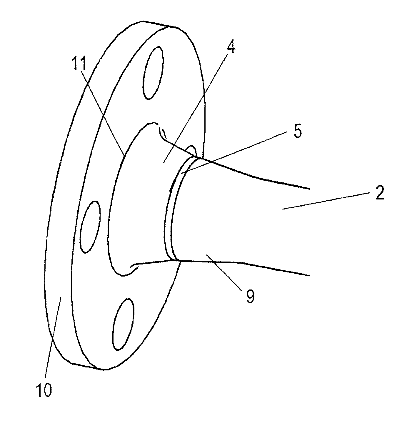
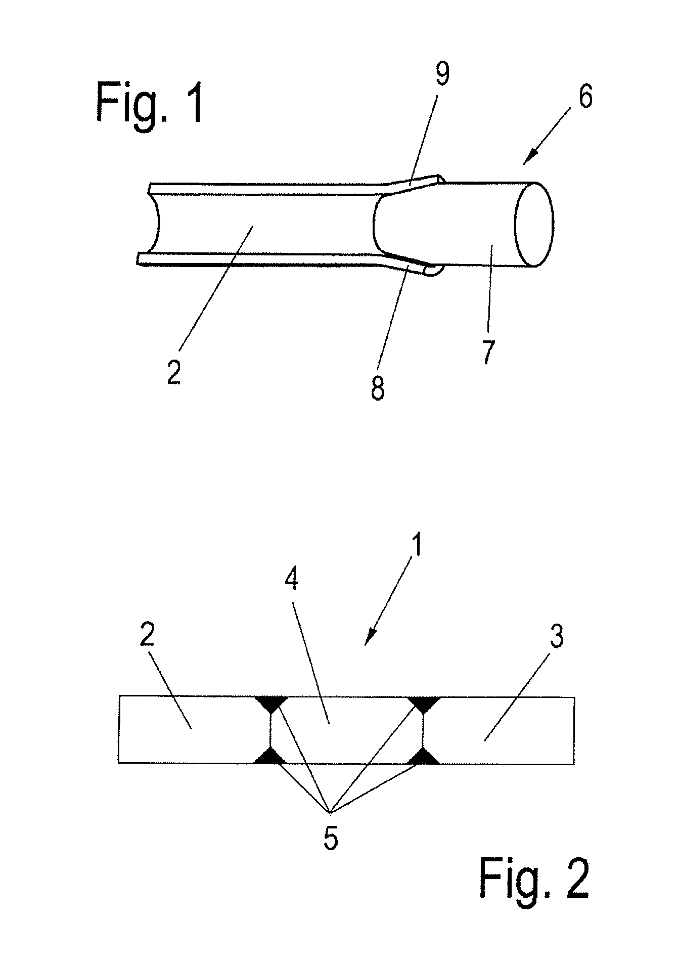
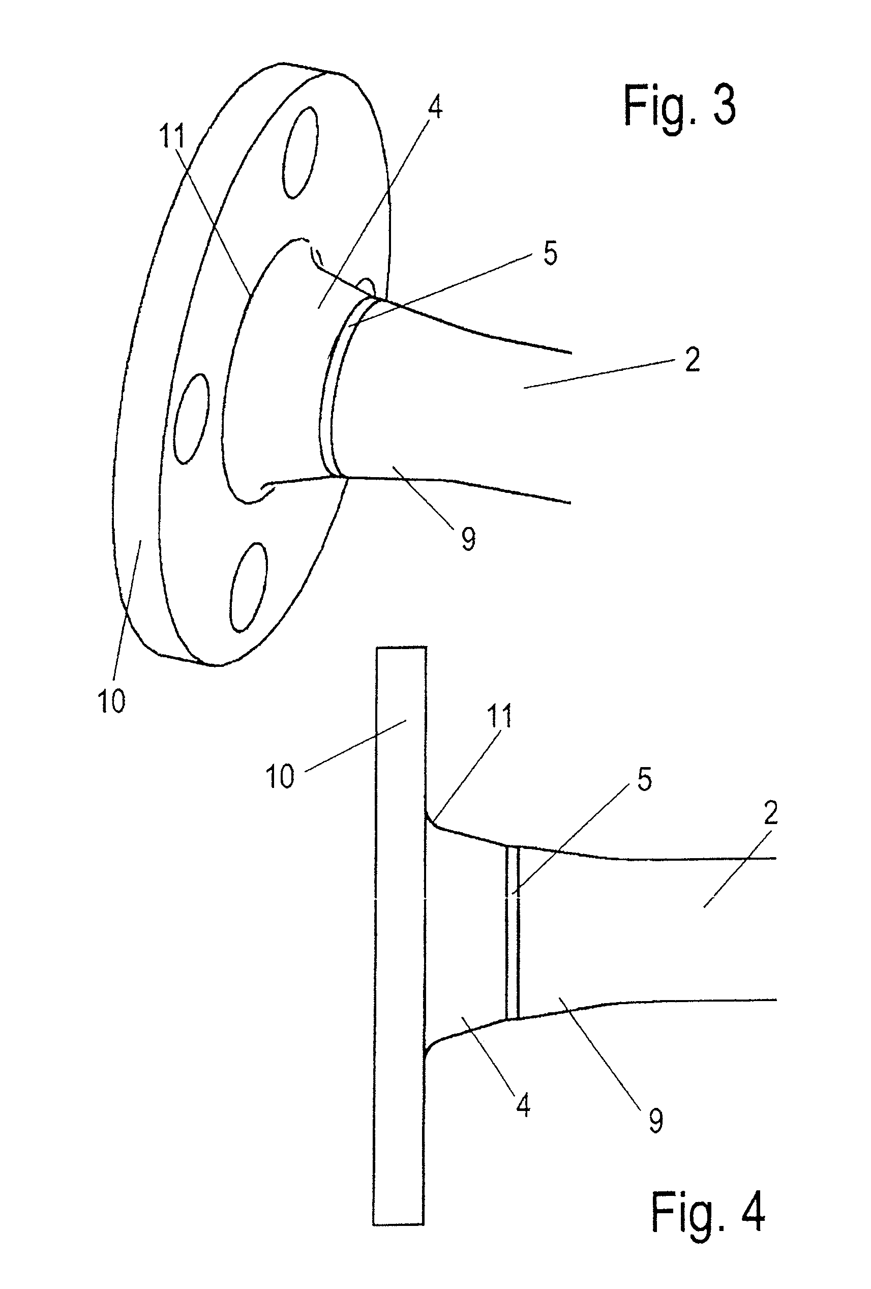
[0022]A divided tube stabilizer 1 includes two tube stabilizer parts 2, 3 and an intermediate element 4 arranged between the two tube stabilizer parts 2, 3. The intermediate element 4 can be constructed, for example, as part of an active stabilizer as an actuator or, in the case of a shiftable stabilizer, as a shift transmission. In an embodiment according to the present disclosure, a circular-ring-shaped cross-section of the tube stabilizer parts 2, 3 may have a constant construction over their entire length or a cross-section which changes in sections, for example, for forming stable sections of the tube stabilizer parts 2, 3 or for saving material on less stressed sections of the tube stabilizer parts 2,3. The changing of the cross-section of a tube stabilizer part 2, 3 may include an enlargement or a reduction of the inside or outside diameters of the tube stabilizer part 2, 3.

[0023]As illustrated in FIG. 1, the tube stabilizer parts 2, 3 have widened sections 9 at their ends fa...


PUM

PropertyMeasurementUnit
Forceaaaaaaaaaa
Circumferenceaaaaaaaaaa

Abstract

A process for connecting a tube stabilizer part of a divided tube stabilizer with an intermediate element, such as an actuator or shift transmission. The process steps include providing the tube stabilizer part, providing the intermediate element, widening an end-side section of the tube stabilizer part using a conical mandrel, and bending the tube stabilizer part, and connecting the tube stabilizer part with the intermediate element.

Description

BACKGROUND OF THE INVENTION[0001]This is an application claiming priority to and benefit of German Patent Application Number 10 2009 026 246.6 filed Jul. 24, 2009 in Germany, the subject matter of which is incorporated by reference herein.BACKGROUND SUMMARY[0002]The present disclosure relates to a process for connecting a tube stabilizer part of a divided tube stabilizer with an intermediate element, and to a corresponding tube stabilizer.[0003]Tube stabilizers are used in the case of motor vehicles as a torsion bar between the two wheels of an axle. They have the purpose of limiting the roll of the vehicle during the reciprocal compression of the wheels of an axle. When a tube stabilizer is active, an actuator is used between two torsion bars, which actuator can actively influence the roll of the vehicle. When, in the case of major torsional stress, the angular deflection of a one-piece stabilizer is not sufficient, a shiftable clutch is placed between the two stabilizer parts.[000...

Claims


Application Information

Patent Timeline
IPC IPC(8): B32B1/08B23K31/02B23P11/00B21D19/00
CPCB21D41/02B60G21/055B60G2202/135B60G2206/012Y10T29/49826B60G2206/81B60G2206/8103B60G2206/8201Y10T428/13B60G2206/427
Inventor HAMMELMAIER, ULLRICHJANZEN, ANREASSAGGEL, SEBASTIANKLEINE, MARKUS
Owner BENTELER AUTOMOBILTECHNIK GMBH
Why Eureka
Try Eureka