
Card with embedded image

a composite card and image technology, applied in the field of composite card manufacturing, can solve the problems of pattern dispersion, image not clear and well defined, and image distortion

Active Publication Date: 2011-01-27
COMPOSECURE LLC
View PDF15 Cites 41 Cited by
  • Summary
  • Abstract
  • Description
  • Claims
  • Application Information

AI Technical Summary

Benefits of technology

[0008]Generally, the lamination of the first and second assemblies is conducted at a lower temperature than the lamination of the first assembly so as to not soften the first conformable layer and hence disturb the fixed image formed on (and in) the deformable layer.
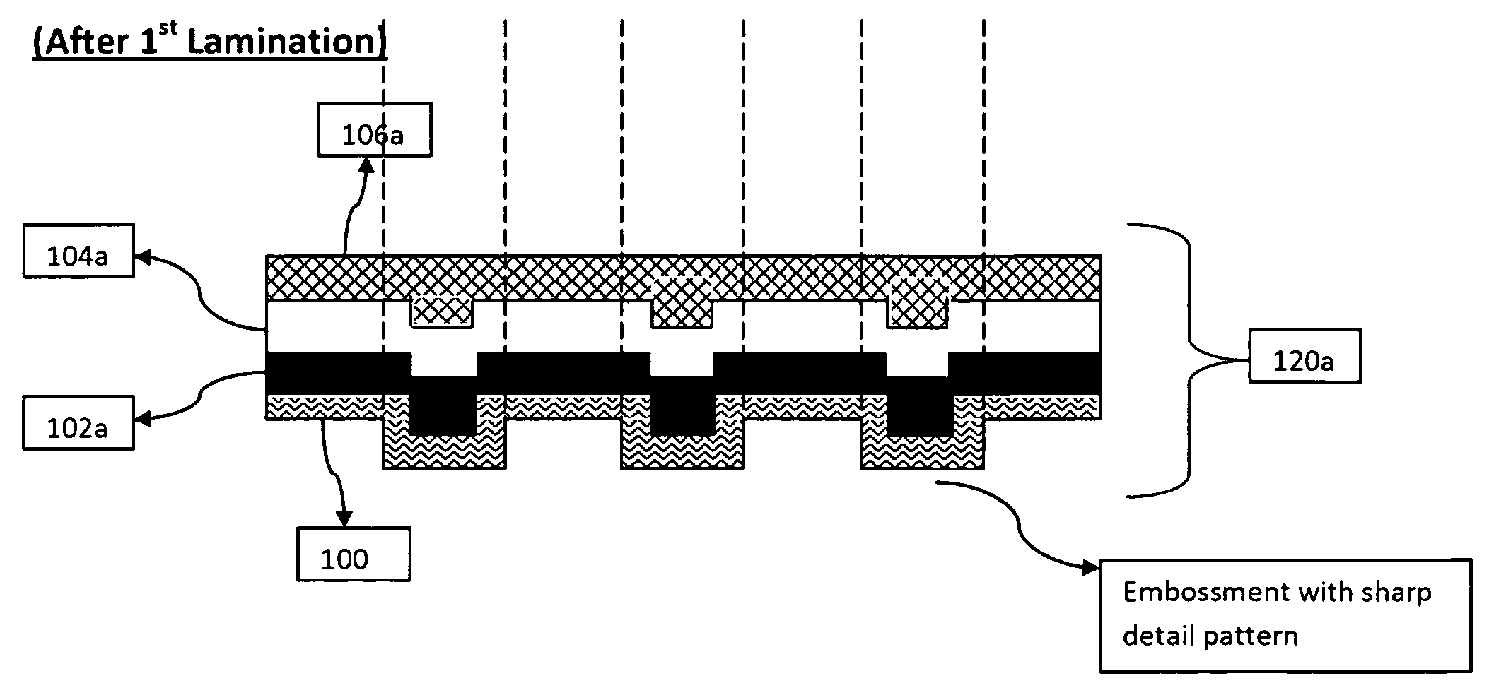
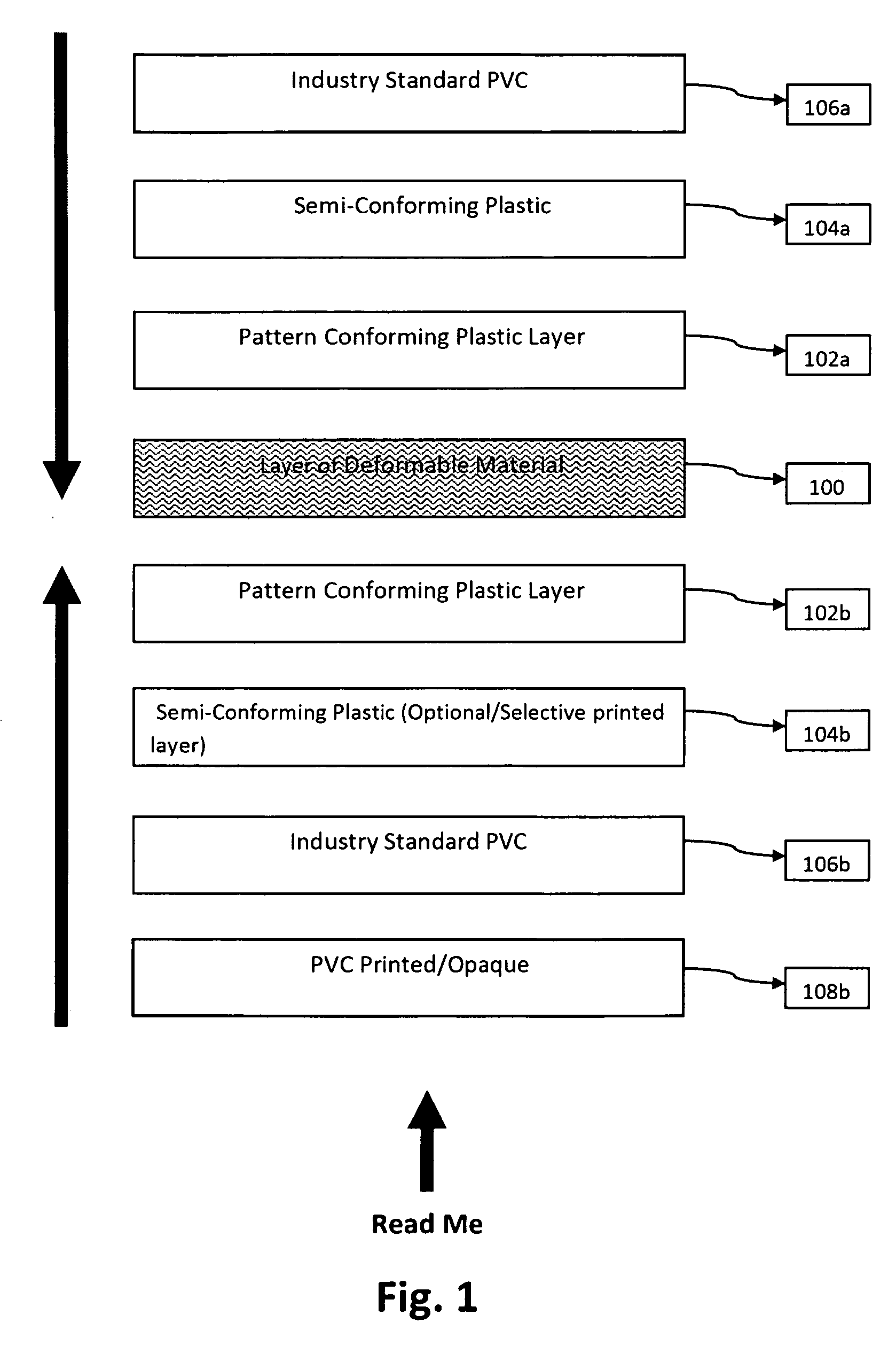
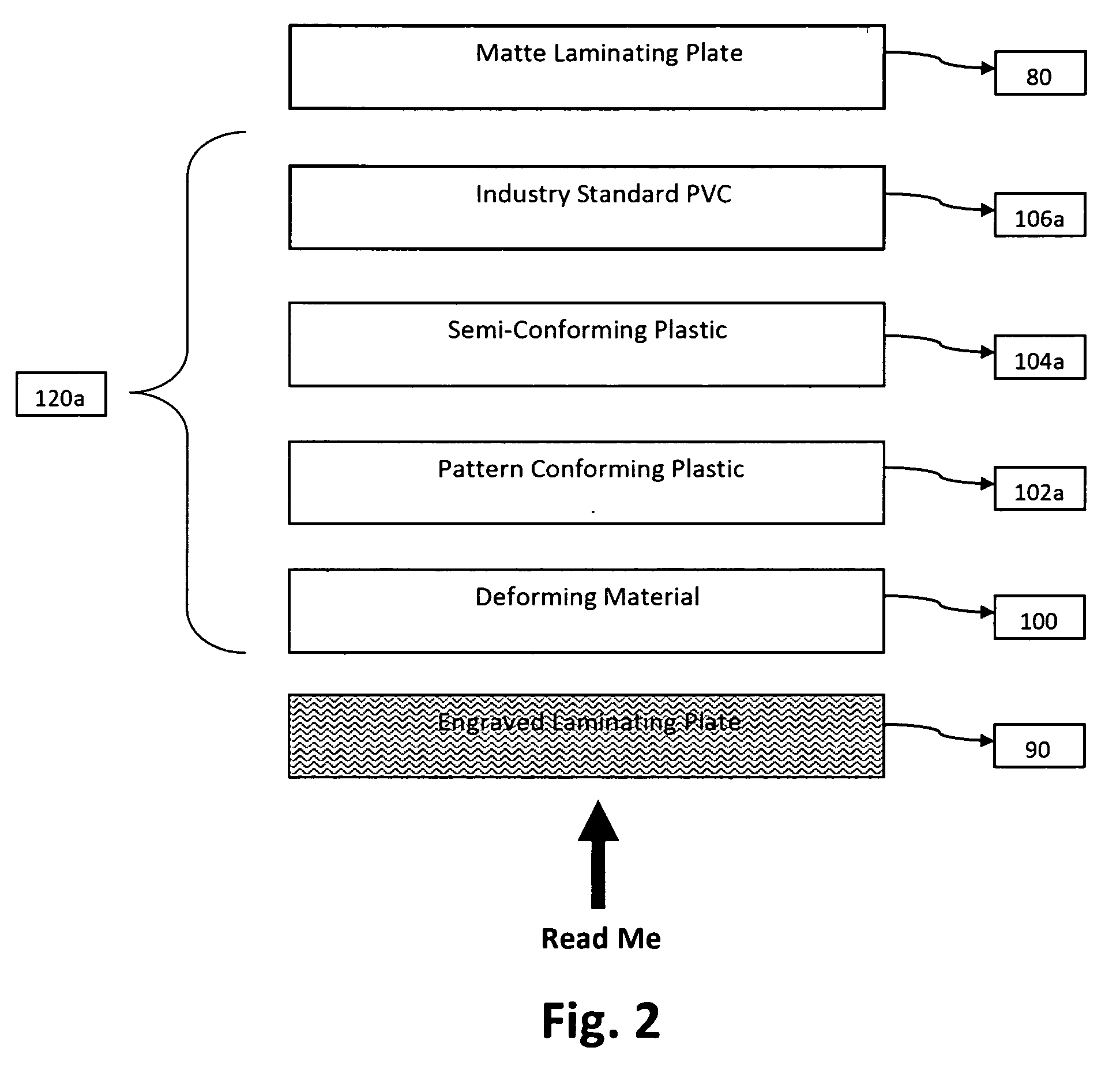
[0015]An embodiment of the invention includes: (a) forming a first assembly which includes a layer of deformable material with a first layer of conforming material overlying the deformable layer and a first set of additional semi conforming and leveling layers overlying layer the first layer; (b) engraving the layer of deformable material and laminating the first assembly for embossing a pattern onto the deformable layer at a relatively high temperature (e.g., 300 degrees Fahrenheit); and (c) forming a second assembly which includes a second layer of conforming material underlying the deformable layer and a second set of additional semi conforming and leveling layers underlying (and being in front of) the second layer and laminating the second assembly with the first assembly at a lower temperature (e.g., 280° F.) to not disturb (re-soften) the embossed pattern.

Problems solved by technology

There is distortion (spread) of the pattern during the transfer since the print pattern is being forced into the deformable layer and the underlying conformable layer.
However, this embossment does not have sharp edges and a resulting image will not be clear and well defined.

Method used


Image

  • Card with embedded image
  • Card with embedded image
  • Card with embedded image

Examples


Embodiment Construction

[0028]FIG. 1 shows the structure of a card embodying the invention which projects a three dimensional (3-D) image or pattern while actually having uniformly flat top and bottom external surfaces. A layer 100, embedded between two layers 102a and 102b of conformable material, is embossed with a desired pattern. A layer 102a of conforming material is formed above layer 100 and a layer 102b also of conforming material is formed below layer 100. The layer 100 is formed of a material which is deformable and malleable. The material of layer 100 may be metallic (e.g., a foil) or any other suitable non-metallic material having a sufficiently high reflective or refractive index to enable the formation and display of a well defined optical contrasting image. The deformable embedded layer 100 can be plain metal, holographic (including HRI), registered holographic, dyed in color, printed, or any combination of the above. To produce a visible image, the deformable layer and the overlying and und...


PUM

PropertyMeasurementUnit
Thicknessaaaaaaaaaa
Thicknessaaaaaaaaaa
Thicknessaaaaaaaaaa

Abstract

The invention includes a method for forming a card with an embedded three dimensional (3-D) image and the resultant card formed by the method. The method includes forming a first assembly which includes a layer of deformable material and an overlying layer of pattern conforming material. An engraved laminating plate is applied to the deformable layer during an engraving and laminating step applied to the first sub-assembly under predetermined pressure and selected temperature conditions for embossing the deformable layer with a well defined and sharp pattern. Then, a second assembly including a pattern conforming layer is laminated with the first assembly to embed and secure the pattern between the two conformable layers.

Description

BACKGROUND OF THE INVENTION[0001]The invention relates to the manufacture of a multi-layered (composite) card, or any like instrument or document.[0002]The term “card” or “cards” as used herein, and in the appended claims, is intended to include a large variety of documents and instruments such as transactional (financial) cards, identification (including a National ID or Driver's License) cards, electronic passport pages, gift cards, documents for holding permanent and long lasting records such as medical records or security cards, or other plastic cards used for promotion of a product or organization.[0003]A known scheme for providing a card with an image includes a screen printed image and the use of clear ultra violet (UV) cured screen printing to create a depression of the metallic foil during lamination. A process for making such a card and some of the features of such a card is illustrated with respect to FIG. 5. As shown in FIG. 5, a deformable metal layer 500 may have a pat...

Claims


Application Information

Patent Timeline
IPC IPC(8): B32B3/30B32B37/02B32B37/14
CPCB32B3/30Y10T428/24529B32B27/06B32B27/08B32B27/30B32B27/32B32B27/36B32B37/003B32B37/02B32B38/06B32B38/14B32B38/145B32B2307/416B32B2307/418B32B2309/68B32B2425/00B32B2429/00B42D2033/10B42D2033/18B42D2033/20B42D2033/24B42D25/425B42D25/00B42D25/45B42D25/328B32B15/08B42D25/46
Inventor HERSLOW, JOHNDASILVA, LUIS J.
Owner COMPOSECURE LLC
Learn More