
Fuel cell system and method of controlling the same

a fuel cell and system technology, applied in the field of fuel cell systems, can solve problems such as the degradation of the output performance of the fuel cell

Active Publication Date: 2011-01-27
TOYOTA JIDOSHA KK
View PDF5 Cites 35 Cited by
  • Summary
  • Abstract
  • Description
  • Claims
  • Application Information

AI Technical Summary

Benefits of technology

The invention provides a fuel cell system that ensures efficient warm-up of the fuel cell while driving a load, such as a drive motor, using the electric power generated by the fuel cell. The system uses a warm-up electric power generation means that performs warm-up electric power generation with lower efficiency than normal electric power generation. The warm-up control means controls the operation state of the fuel cell during warm-up electric power generation based on a correlation between the system loss required for warm-up and the warm-up output required for driving the load. This ensures the fuel cell operates at the most efficient state for both the system loss and the warm-up output. The fuel cell system is controlled on the basis of a predetermined index, which is determined by the purpose of warm-up, such as preventing moisture refreezing or ensuring rapid warm-up. The warm-up control means adjusts the operation state of the fuel cell accordingly to achieve both the system loss and the warm-up output. This efficient control of the fuel cell system ensures efficient warm-up while driving a load.

Problems solved by technology

On the other hand, in the latter warm-up electric power generation, electric power generation is performed when the fuel cell needs to be warmed up, for example, when moisture in the fuel cell freezes through the exposure to a low-temperature environment and the output performance of the fuel cell has deteriorated.

Method used


Image

  • Fuel cell system and method of controlling the same
  • Fuel cell system and method of controlling the same
  • Fuel cell system and method of controlling the same

Examples


Embodiment Construction

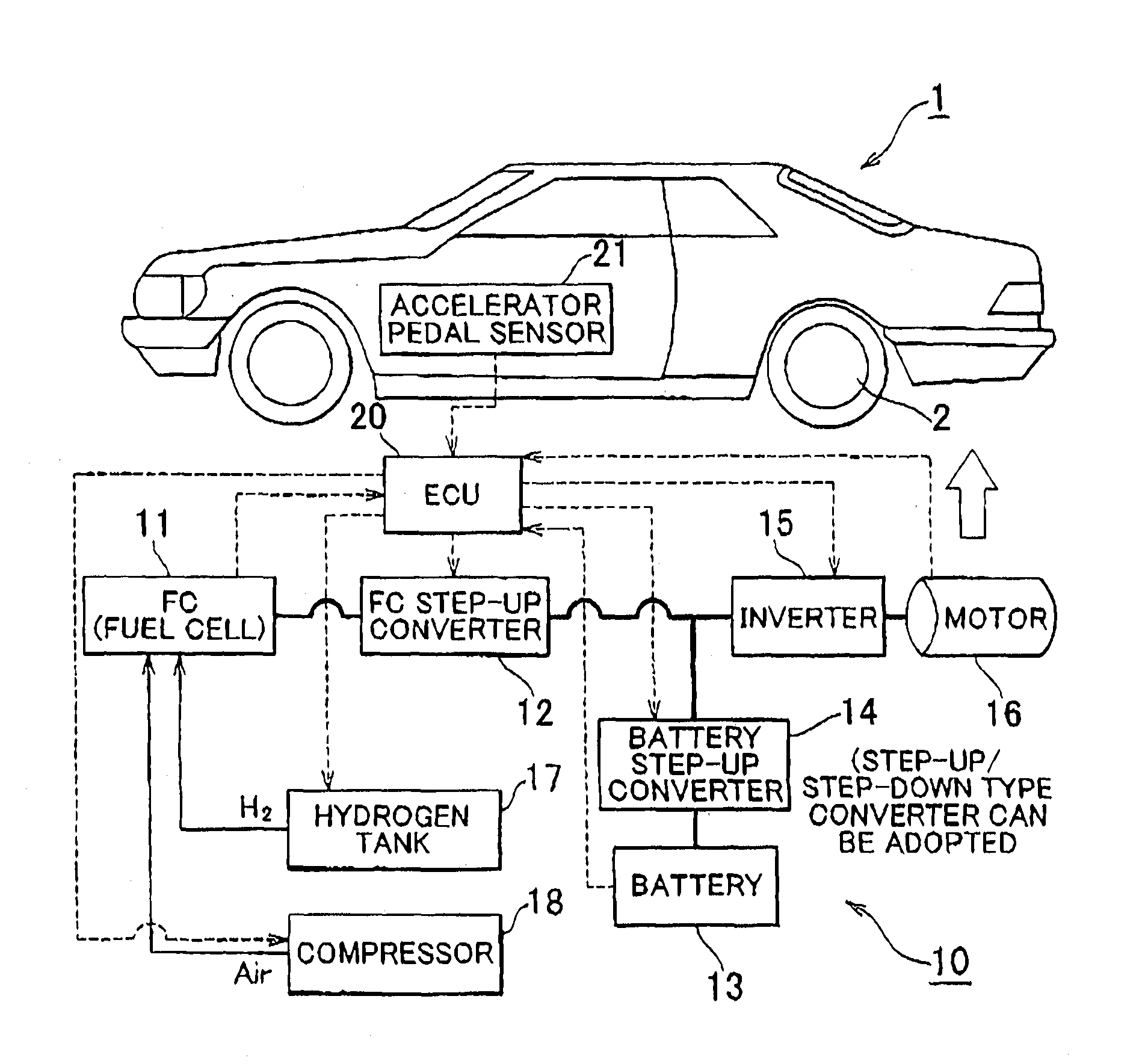
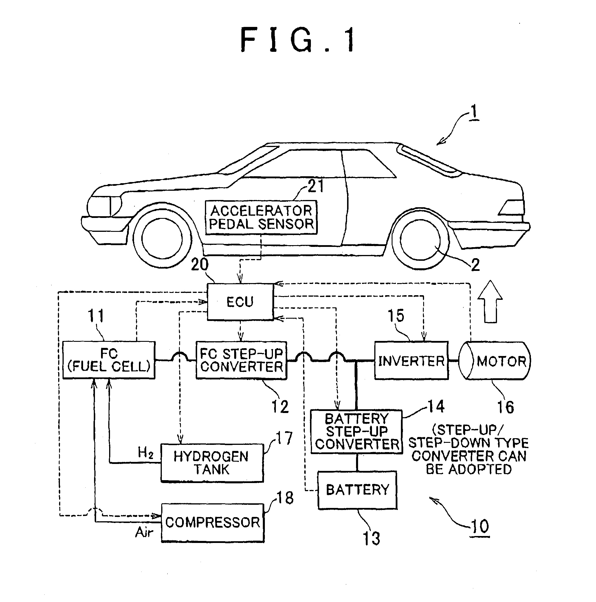
[0041]An embodiment of a fuel cell system 10 according to the invention will be described in detail on the basis of the drawings. The fuel cell system 10 according to this embodiment of the invention supplies electric power to a drive motor 16 as a drive unit of a vehicle 1 as a mobile object, but is also applicable to a mobile object other than the vehicle 1, such as a ship, a robot, or the like, or an object that does not move but needs to be supplied with electric power.

[0042]FIG. 1 schematically shows an overall configuration of the fuel cell system 10, and the vehicle 1 as a mobile object that uses electric power supplied from the fuel cell system 10 as a drive source. The vehicle 1 runs by itself and can move through the driving of driving wheels 2 by a drive motor (hereinafter referred to simply as “the motor”) 16. This motor 16 is a so-called three-phase motor, and is supplied with alternating electric power from an inverter 15. In addition, this inverter 15 is supplied with...


PUM

PropertyMeasurementUnit
temperatureaaaaaaaaaa
speedaaaaaaaaaa
current densityaaaaaaaaaa

Abstract

A fuel cell system is equipped with a drive motor, a fuel cell, normal electric power generation means for performing normal electric power generation under a condition that the fuel cell is not warmed up, warm-up electric power generation means for performing warm-up electric power generation with lower electric power generation efficiency than normal electric power generation, and warm-up control means for controlling performance of warm-up electric power generation by the warm-up electric power generation means on a basis of a predetermined index on a necessity to warm up the fuel cell. The warm-up control means controls an operation state of the fuel cell during warm-up electric power generation on a basis of a correlation between the system loss required for warm-up of the fuel cell and a warm-up output required for driving of a load including the drive motor during warm-up of the fuel cell.

Description

BACKGROUND OF THE INVENTION[0001]1. Field of the Invention[0002]The invention relates to a fuel cell system that supplies a drive motor with electric power from a fuel cell generating electric power in an electrochemical reaction, and a method of controlling the fuel cell system.[0003]2. Description of the Related Art[0004]In recent years, fuel cells have been drawing attention as electric power supplies excellent in operation efficiency and environment friendliness. A fuel cell controls the amount of supply of fuel gas and outputs an electric power corresponding to a request from a drive motor. In some cases, however, as a result of a response delay in the amount of supply of gas, the responsiveness of the output electric power decreases, and a secondary battery is mounted as compensation. This secondary battery accumulates regenerative energy generated in reducing the speed of the drive motor and electric power generated by the fuel cell, and discharges the accumulated energy for ...

Claims


Application Information

Patent Timeline
Patent Type & Authority Applications(United States)
IPC IPC(8): H01M8/04
CPCH01M8/04589Y02E60/50H01M8/04619H01M8/04731H01M8/04798H01M8/0488H01M8/0494H01M2008/1095H01M2250/20Y02T90/32H01M8/04268H01M8/0432H01M8/04365H01M8/04559H01M8/04604Y02T90/40H01M8/04H01M8/10B60L50/50
Inventor MANABE, KOTAIMANISHI, HIROYUKISAKAJO, YUICHI
Owner TOYOTA JIDOSHA KK
Learn More