Crimping terminal fitting, method of forming it and wire with terminal fitting

a terminal fitting and crimping technology, applied in the direction of line/current collector details, connection formation by deformation, connection effected by permanent deformation, etc., can solve the problems of increasing contact resistance with the wire, plate thickness of the terminal fitting becomes relatively excessive, and the end of the wire barrel cannot properly thrust themselves

Inactive Publication Date: 2011-01-27
SUMITOMO WIRING SYST LTD
View PDF9 Cites 10 Cited by
  • Summary
  • Abstract
  • Description
  • Claims
  • Application Information

AI Technical Summary

Problems solved by technology

Thus, the plate thickness of the terminal fitting becomes relatively excessively large as compared with the wire size if the current capacity is small even though a relatively high strength is required.
Thus, a relatively thick wire barrel is crimpe...

Method used


Image

  • Crimping terminal fitting, method of forming it and wire with terminal fitting
  • Crimping terminal fitting, method of forming it and wire with terminal fitting
  • Crimping terminal fitting, method of forming it and wire with terminal fitting

Examples


first embodiment

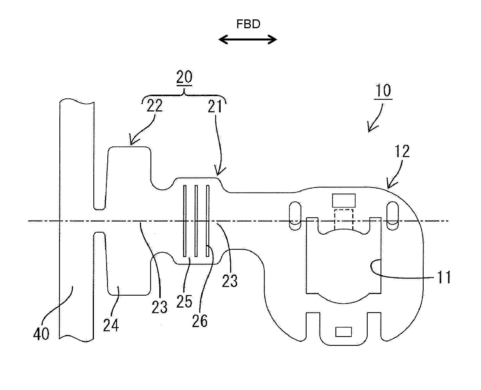
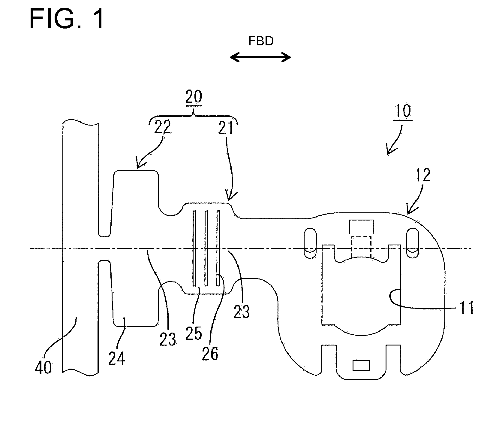
[0041]A crimping terminal fitting 10 in accordance with the invention is identified by the numeral 10 in FIGS. 1 to 5. The crimping terminal 10 is formed by punching out or cutting a conductive metal plate into a specified shape, as shown in FIG. 1, and then bending, folding and / or embossing the cut parts. Lateral directions of FIG. 1 are referred to herein as forward and backward directions FBD.

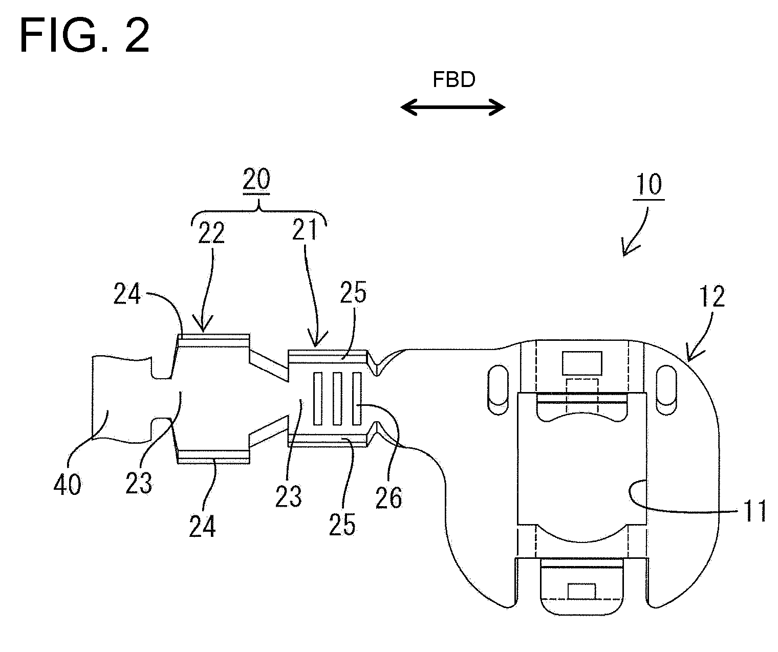
[0042]As shown in FIGS. 2 and 3, an open barrel-shaped wire crimping portion 20 is formed at a front part of the crimping terminal fitting 10 and a ground terminal 12 is formed at a rear part of the crimping terminal fitting 10. The ground terminal 12 is to be fixed, for example, to the body of a vehicle by a bolt (not shown) inserted through a bolt insertion hole 11 while being united with another crimping terminal fitting 10 that may be of substantially the same type. The wire crimping portion 20 has a wire barrel 21 (see FIG. 2) to be crimped, bent or folded into connection with one or mo...

second embodiment

[0076]Although both coating crimping pieces 124 are formed to be relatively thicker than the both core crimping pieces 125 in the second embodiment, they may be formed to be as thin as the core crimping pieces 125 if there is no problem of damage and the like of the insulation coating.


PUM

PropertyMeasurementUnit
Fractionaaaaaaaaaa
Currentaaaaaaaaaa
Digital informationaaaaaaaaaa

Abstract

A crimping terminal fitting has a wire barrel (21) to be crimped and connected to core strands (31) of a wire (30). The wire barrel (21) has a base plate (23) continuously extending from a ground terminal (11) in a longitudinal direction. Two core crimping pieces (25) extend from the opposite sides of the base plate (23). A thinned portion (27) is formed at least at a leading end of each core crimping piece (25) and is thinner than the base plate (23).

Description

BACKGROUND OF THE INVENTION[0001]1. Field of the Invention[0002]The invention relates to a crimping terminal fitting, a method of forming it and a wire with a terminal fitting.[0003]2. Description of the Related Art[0004]Japanese Registered Utility Model Publication No. 3005065 discloses a terminal fitting that is crimped and connected to an end portion of a wire. Terminal fittings of this type are used for wiring in automotive vehicles and the like.[0005]This crimping terminal fitting includes a wire barrel to be crimped and connected to core strands of a wire and an insulation barrel portion to be crimped and connected to an insulation coating of the wire. Both barrels initially are open and are produced by press-working a single metal plate. The wire barrel includes two core crimping pieces. The core crimping pieces are deformed inwardly to wrap around the core strands of the wire and the leading ends of the core crimping pieces thrust themselves between the core strands to compl...

Claims


Application Information

Patent Timeline
IPC IPC(8): H01R4/18H01R43/16
CPCH01R4/185H01R43/048Y10T29/49218Y10T29/49185Y10T29/49204H01R43/16Y10T29/49174Y10T29/49181Y10T29/49222
Inventor UKAI, EIKO
Owner SUMITOMO WIRING SYST LTD
Why Eureka
Try Eureka