Differential having self-adjusting gearing

a gearing and differential technology, applied in the field of differentials, can solve the problems of inability to manufacture deviations, inability to achieve precision in any manufacturing process, and increased cost of manufacturing these devices, and achieve the effect of facilitating smooth operation of meshing gears, relatively low cost, and greater degree of freedom relative to on

Inactive Publication Date: 2011-01-27
EATON CORP
View PDF39 Cites 10 Cited by
  • Summary
  • Abstract
  • Description
  • Claims
  • Application Information

AI Technical Summary

Benefits of technology

[0010]When the shape of the cross pin along its axis or the central bore of the pinion gear are modified in this way, they allow the pinion gear and side gear to self-adjust relative to one another through very small angles, but which results in a greater degree of freedom relative to one another. This increased degree of freedom and self-adjustment capability also compensate for the unavoidable deviations in...

Problems solved by technology

One problem associated with such differentials is the need for the mating surfaces between the pinion gears and the cross pins as well as between the pinion gears and the side gears to smoothly and efficiently interact.
Unfortunately, incre...

Method used


Image

  • Differential having self-adjusting gearing
  • Differential having self-adjusting gearing
  • Differential having self-adjusting gearing

Examples


Embodiment Construction

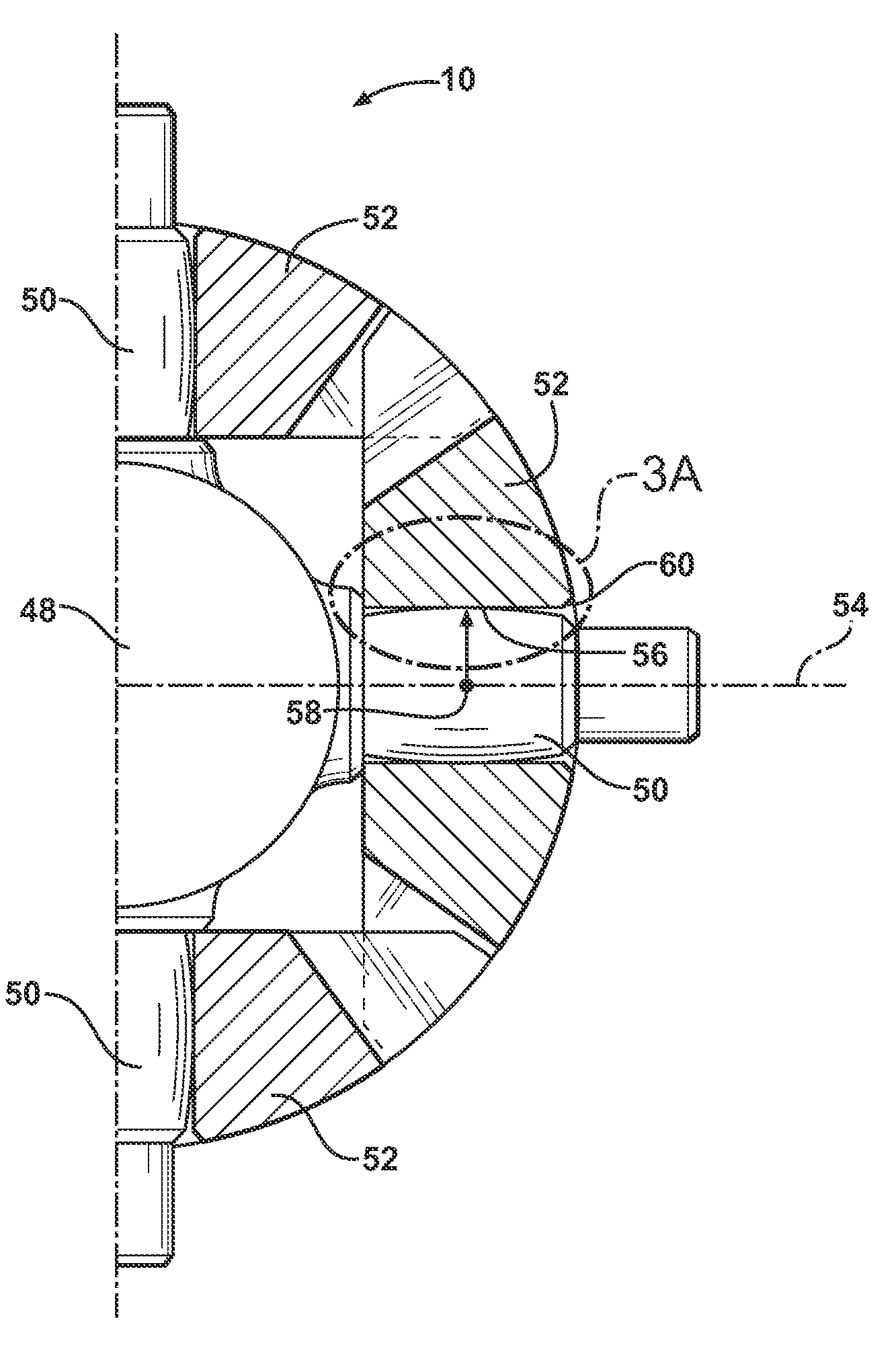
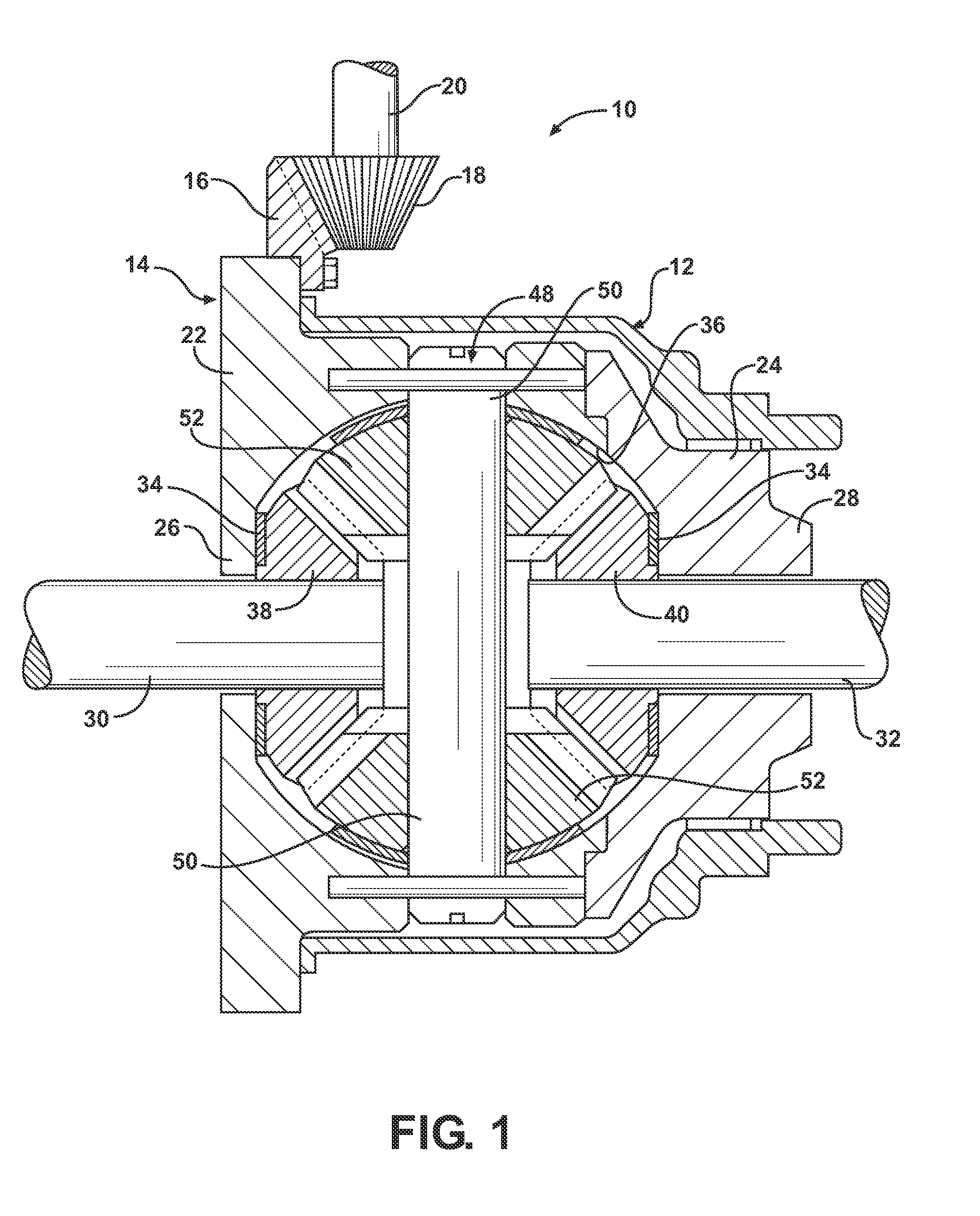
[0019]One representative embodiment of a differential of the type that may employ a spider having a cross pin or pinion gear of the type contemplated by the present invention is generally indicated at 10 in FIG. 1, where like numerals are used to designate like structure throughout the drawings. The differential 10 is designed to be employed as a part of a drive train for any number of vehicles having a power plant that is used to provide motive force to the vehicle. Thus, those having ordinary skill in the art will appreciate that the differential 10 may be employed as a part of a transfer case that operatively couples the front and rear axis of a vehicle, in an open differential, a limited slip differential or locking differential used to couple axle half shafts, as well as other applications commonly known in the art. The limited slip or locking differentials may be hydraulically actuated or electronically actuated and therefore include coupling mechanisms, such as friction clutc...


PUM


Abstract

A differential for use in a vehicle drive train including a gear case that is operatively supported in driven relationship with respect to the drive train and a spider mounted for rotation with the gear case. The spider includes at least one pair of cross pins. Each cross pin defines a longitudinal axis and an outer surface that is convex about an axis extending perpendicular to the longitudinal axis of the cross pin. Pinion gears include a central bore where the cross pins are received in the central bore of the pinion gears such that the gears are mounted for rotation with the spider and in meshing relationship with side gears with an increased degree of rotational freedom of the pinion gears about the convex surface of the cross pin. Alternatively, the central bore of the cross pin may have an inner surface that is convex along the axis of the central bore.

Description

BACKGROUND OF THE INVENTION[0001]1. Field of the Invention[0002]The present invention relates, generally, to differentials, and more specifically to a differential having self-adjusting gearing.[0003]2. Description of the Related Art[0004]Differentials are well known devices used in vehicle drive trains. These devices operate to couple a pair of rotating members, such as drive shafts or axle half shafts about a rotational axis. Thus, differentials have been employed as a part of transfer cases that operatively couple the front and rear axles of a vehicle, in open differentials as well as limited slip and locking differentials used to couple axle half shafts, and other applications commonly known in the art.[0005]Differentials of the type known in the related art may include a housing and a gear case that is operatively supported by the housing for rotation by a vehicle drive train. The differential typically includes at least a pair of side gears. The side gears are splined for rota...

Claims


Application Information

Patent Timeline
IPC IPC(8): F16H48/08
CPCF16H2048/085F16H48/08F16H1/48
Inventor RADZEVICH, STEPHEN P.
Owner EATON CORP
Why Eureka
Try Eureka