

Distributed spectrum sensing
- Summary
- Abstract
- Description
- Claims
- Application Information
AI Technical Summary
Benefits of technology
Problems solved by technology
Method used
Image

Examples
first embodiment
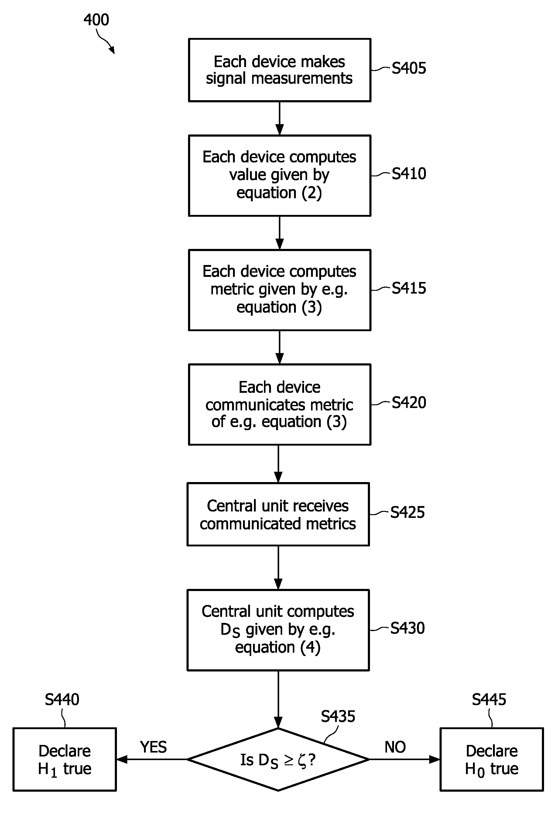
[0033]FIG. 1 shows a schematic block diagram illustrating the arrangement of an exemplary system 100 according to the The system 100 can comprise a transmitter 105, first to M-th devices 110_1 to 110_M distributed over a region, and a central unit 140. Each of the devices 110_1 to 110_M may include an antenna, a sensing unit, a first computing unit, a second computing unit and a communicating unit. That is, an i-th device 110—i can comprise an antenna 115—i, a sensing receiver or unit 120—i, a first computing unit 125—i, a second computing unit (130_i) and a communicating unit 135—i. For example, the first device 110_1 may include an antenna 115_1, a sensing unit 120_1, a first computing unit 125_1, a second computing unit (130_1) and a communicating unit 135_1, and the M-th device 110_M can comprise an antenna 115_M, a sensing unit 120_M, a first computing unit 125_M, a second computing unit (130_M) and a communicating unit 135_M.
[0034]A device 110—i can have a structure different...
second embodiment
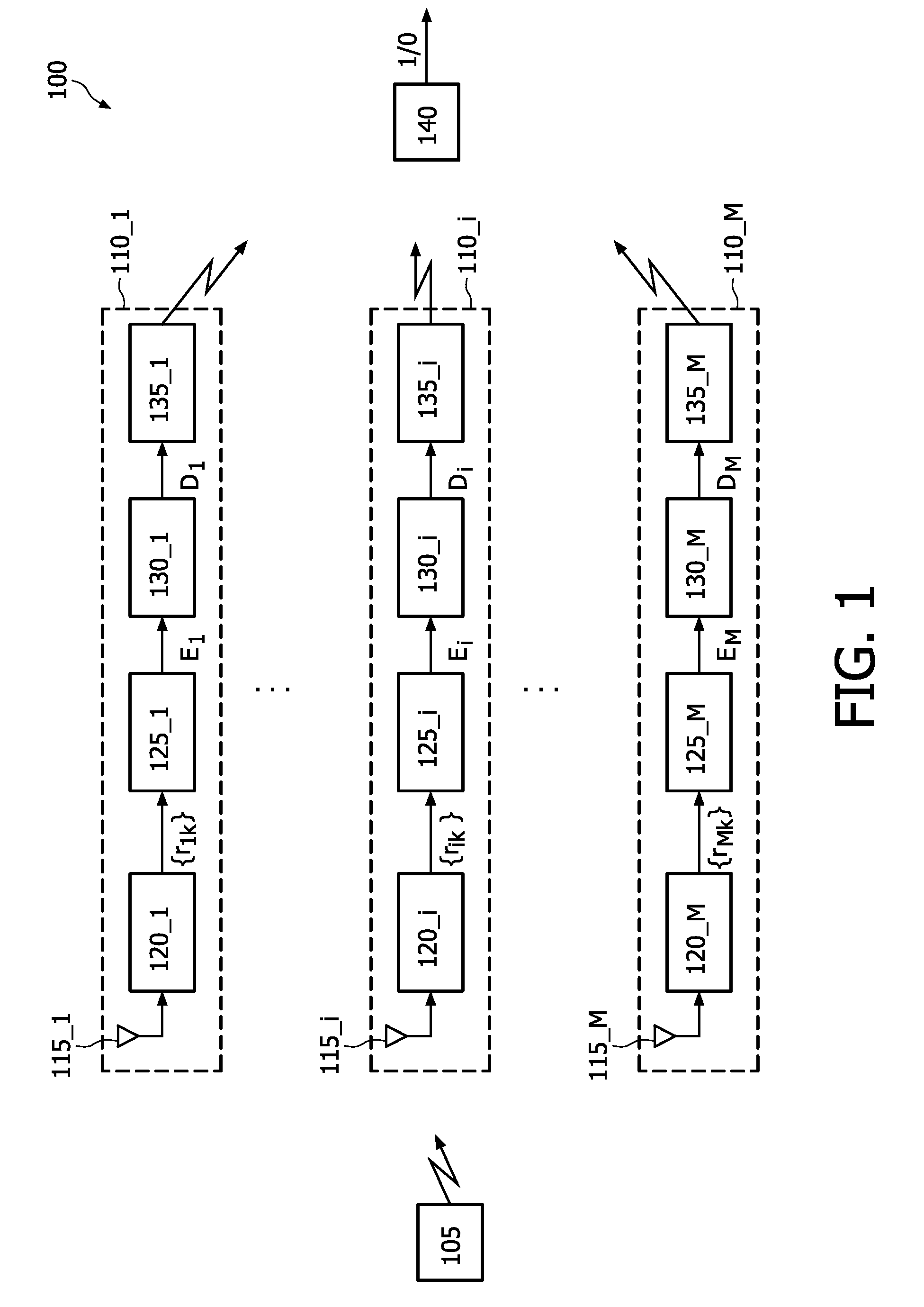
[0057]Devices or sensors of a sensor network can for instance be distributed over a human or animal body. The hypothesis H1 in this case may represent a presence (an occurrence), or a deviation from a normal value, of a physiological source or parameter. On the other hand, the hypothesis H0 can represent its absence, or being at the normal state. For example, H0 and H1 may represent a normal heartbeat and a heart arrhythmia of a person.
[0058]The steps described in connection with the first embodiment remain similar with the appropriate changes in nomenclature, with the difference that the underlying probability distributions under the hypotheses H0 and H1 can now be different depending on the statistical nature of the event to be detected.
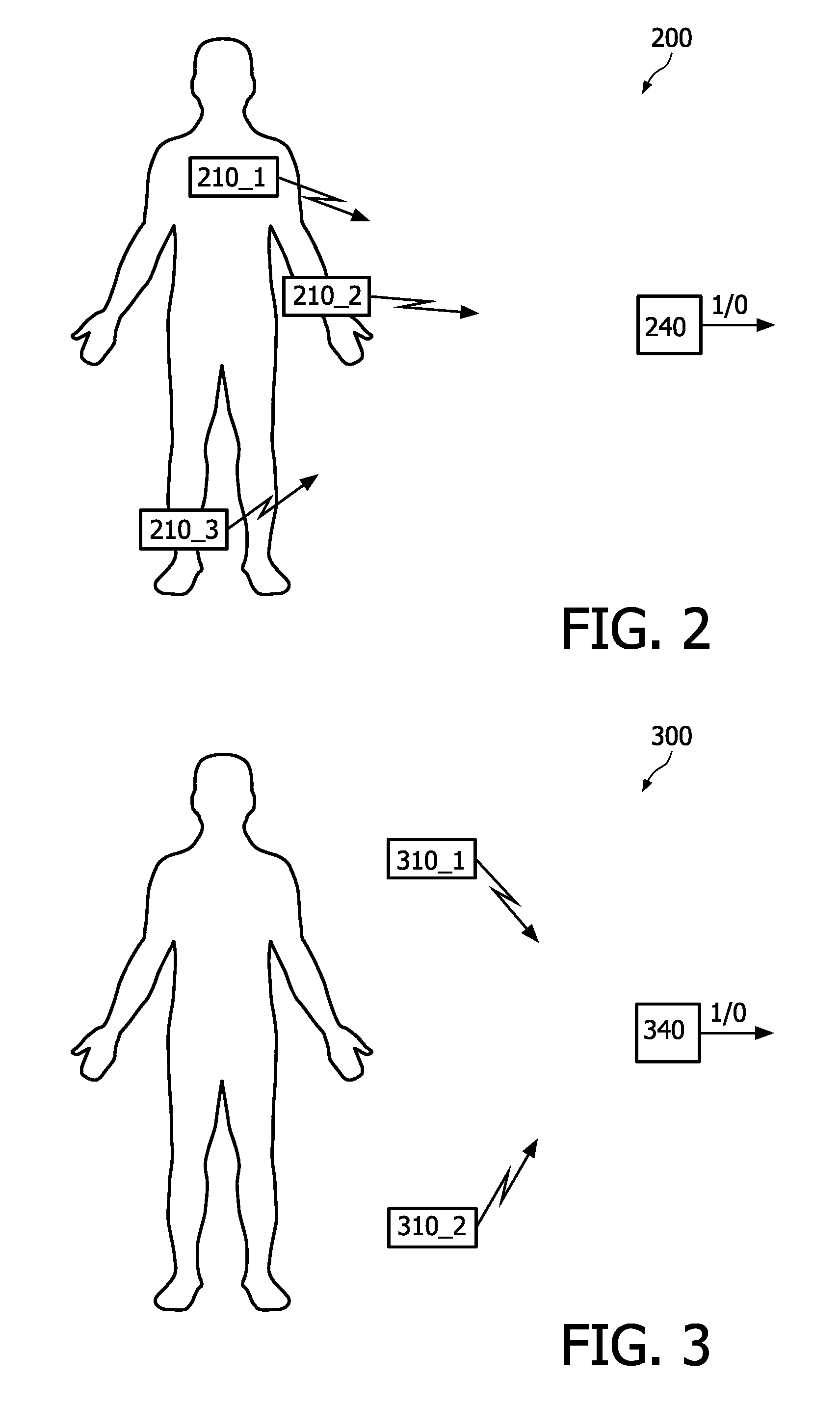
[0059]FIG. 3 shows a schematic block diagram illustrating the arrangement of an exemplary system 300 according to the third embodiment. The system 300 can comprise a plurality of devices, e.g. first and second devices 310_1 and 310_2, and a centra...
PUM
 Abstract
Description
Claims
Application Information