Support pedestal for supporting an elevated building surface

a technology for supporting pedestals and buildings, applied in the field of supporting pedestals, can solve the problems of threadably attached couplers, affecting the strength of the support pedestal and the coupler(s), and affecting so as to increase the obtainable height increase and enhance the stability of the support pedestal

Active Publication Date: 2011-02-03
UNITED CONSTR PROD LLC
View PDF26 Cites 34 Cited by
  • Summary
  • Abstract
  • Description
  • Claims
  • Application Information

AI Technical Summary

Benefits of technology

[0026]In one aspect, the engagement of the first and second locking members may operatively synchronize the base member threads and the coupling member threads, and may prevent rotation of the coupling member relative to the base member. In another aspect, the support member threads may be adapted to concurrently threadably engage with the coupling member threads and the base member threads. In this manner, the support member may be threadably engaged along the entire length of the coupling member and concurrently threaded onto the base member.
[0027]In another aspect, the first locking member may include at least one elongated rib and the second locking member may include at least one elongated slot, where the rib is adapted to slidably engage within the elongated slot when the first cylindrical engagement portion is inserted into the base member bore to operatively synchronize the base member threads. The engaged rib and slot may also prevent rotation of the base member relative to the coupling member.
[0028]In one aspect, the engagement of the first and second locking members may inhibit axial movement of the coupling member relative to the base member. In this manner, the coupling member will be fixed to the base member in a manner that enhances the stability of the support pedestal. For example, the first locking member may include a tab aperture and the second locking member may include a resilient tab member, whereby the tab member is adapted to engage the tab aperture when the first cylindrical engagement portion is inserted into the base member bore, such as to operatively align and synchronize the base member threads with the coupling member threads and to prevent rotation of the base member relative to the coupling member. In another refinement, the first locking member may also include a pair of elongated ribs forming at least one track and the resilient tab member may be adapted to slidably engage within the track when the first cylindrical engagement portion is inserted into the base member bore. In this regard, the tab aperture may be disposed within the track to engage the tab member.
[0029]According to another aspect, the length of the cylindrical support extension may be greater than the length of the second cylindrical engagement portion. In this manner, the support member can optionally be in concurrent threaded engagement with both the coupling member and the base member. According to another aspect, a second coupling member may be utilized to operatively couple the support member to the base member. The use of a second coupling member can advantageously further increase the obtainable height of the support pedestal. According to another aspect, the cylindrical base extension may include a third locking member that is disposed on the cylindrical base extension wall and the first cylindrical engagement portion may include a fourth locking member. The utilization of additional locking members can further increase the stability of the support pedestal.

Problems solved by technology

Coupler members such as the coupler member disclosed in U.S. Pat. No. 5,588,264 can be used to increase the useful height of a support pedestal; however, one deficiency of threadably attached couplers is that the strength of the support pedestal and coupler(s) is dependent on the number of threads in mutual engagement in the pedestal as a whole.
A second deficiency of threadably attached couplers is the time required for a builder to adequately engage the threads of the coupler with the threads of additional couplers and with the threads of the pedestal.
A third deficiency of threadably attached couplers is that there are sometimes gaps in the height adjustment range that require the use of different pedestals to achieve a specific height.

Method used


Image

  • Support pedestal for supporting an elevated building surface
  • Support pedestal for supporting an elevated building surface
  • Support pedestal for supporting an elevated building surface

Examples


Embodiment Construction

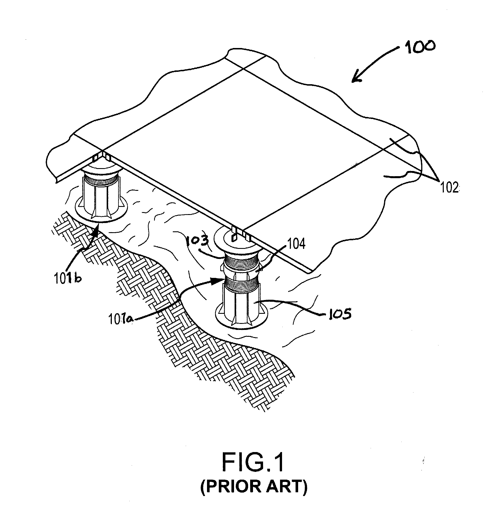
[0045]FIG. 1 illustrates a plurality of conventional support pedestals 101a, 101b supporting a plurality of surface tiles 102 to form a building surface assembly 100. An example of a support pedestal of this design is illustrated, for example, in U.S. Pat. No. 5,588,264 by Buzon which is hereby incorporated by reference. As is illustrated in FIG. 1, the support pedestals 101a, 101b can be placed on a fixed surface and support a plurality of surface tiles 102 above the fixed surface.

[0046]To create a building surface that reduces or eliminates the fluctuations in the fixed uneven surface beneath it, the support pedestals 101a, 101b may have different heights. For example, the support pedestal 101a has a height that is greater than the height of the support pedestal 100b due to a slope in the fixed surface beneath the support pedestals. In this regard, the support pedestal 100a includes a coupling member 104. The coupling member 104 includes internal threads into which a support membe...


PUM


Abstract

A method and device for supporting a structure above a fixed surface. The device can include a support pedestal whose height is adjustable through a range of heights without a substantial gap in the obtainable heights. In one embodiment, the support pedestal can include a base member, a support member and a coupling member operatively connecting the base member and the support member. The coupling member can include first and second cylindrical walls, whereby an outer wall of the coupling member bears directly on an outer wall of the base member. Locking members can be utilized to operatively attach the coupling member to at least one of the base member or the support member. The locking members can function to increase the structural stability of support pedestal.

Description

BACKGROUND OF THE INVENTION[0001]1. Field of the Invention[0002]This invention relates to the field of support pedestals for supporting an elevated surface above a fixed surface, such as for elevated floors, decks and walkways.[0003]2. Description of Related Art[0004]Elevated building surfaces such as elevated floors, decks, terraces and walkways are desirable in many environments. One common system for creating such surfaces includes a plurality of surface tiles, such as concrete tiles (pavers), stone tiles or wood tiles, and a plurality of spaced-apart support pedestals upon which the tiles are placed to be supported above a fixed surface. For example, in outdoor applications, the surface tiles may be elevated above a fixed surface by the support pedestals to promote drainage, to provide a level structural surface for walking, and / or to prevent deterioration of or damage to the surface tiles forming the building surface. The support pedestals can have a fixed height, or can have a...

Claims


Application Information

Patent Timeline
Patent Type & Authority Applications(United States)
IPC IPC(8): B66F3/08E04B1/35
CPCB66F3/08E04F15/0247E04F15/02183E04F2015/02127
Inventor KNIGHT, III, STEPHEN J.KUGLER, WILLIAM E.
Owner UNITED CONSTR PROD LLC
Why Eureka
Try Eureka