Micromechanical yaw-rate sensor

a micro-mechanical and sensor technology, applied in the direction of acceleration measurement using interia force, turn-sensitive devices, instruments, etc., can solve the problem of insufficient detection of rotation around two rotational axes

Active Publication Date: 2011-02-03
ROBERT BOSCH GMBH
View PDF13 Cites 41 Cited by
  • Summary
  • Abstract
  • Description
  • Claims
  • Application Information

AI Technical Summary

Benefits of technology

[0015]It may be advantageous for the mechanical properties if the first yaw-rate sensor element and the second yaw-rate sensor element have a congruent mirror plane or form a rotationally symmetric or mirror-symmetric system.

Problems solved by technology

For many applications, however, it is insufficient to detect the rotation around two rotational axes.

Method used


Image

  • Micromechanical yaw-rate sensor
  • Micromechanical yaw-rate sensor
  • Micromechanical yaw-rate sensor

Examples


first exemplary embodiment

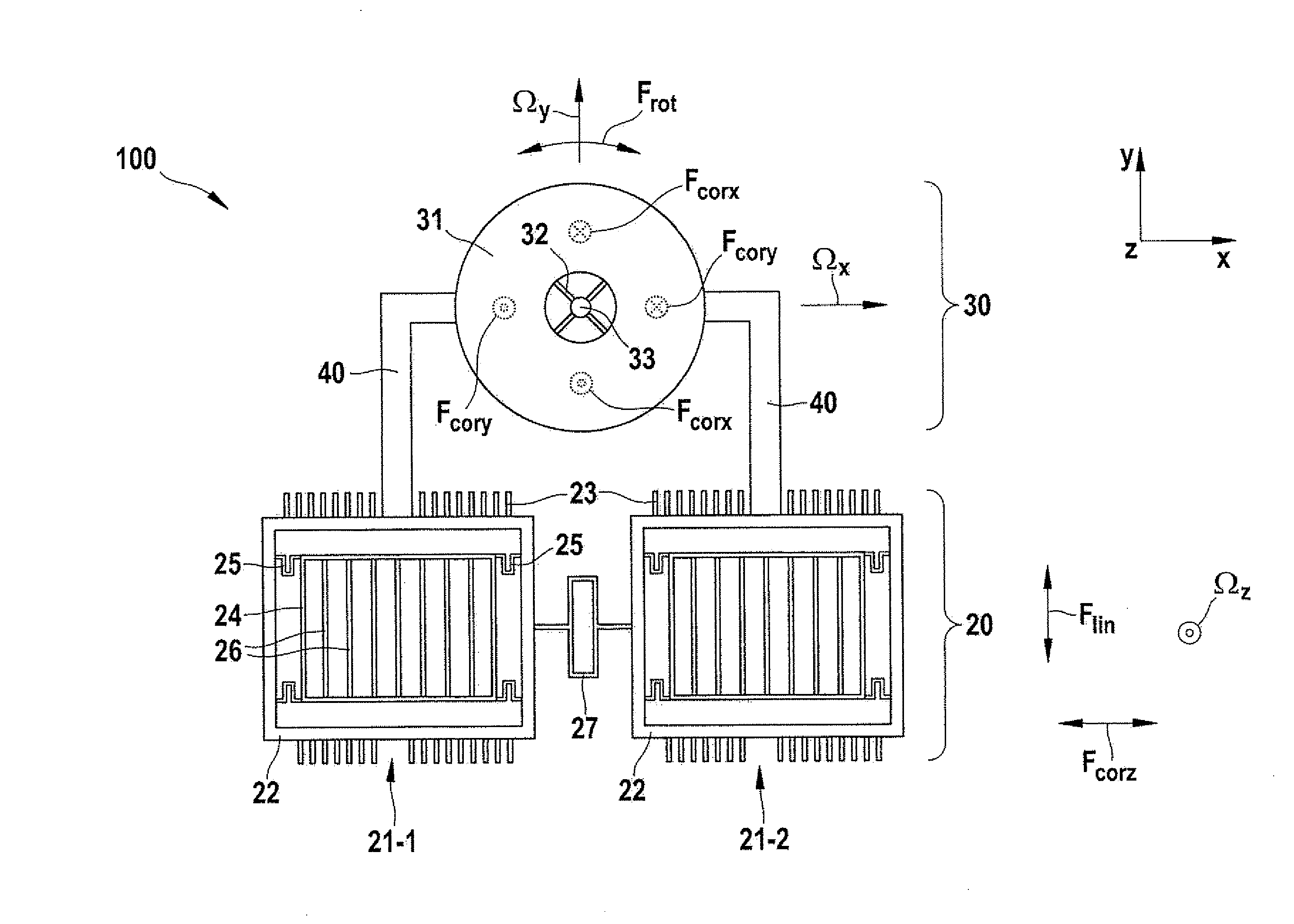
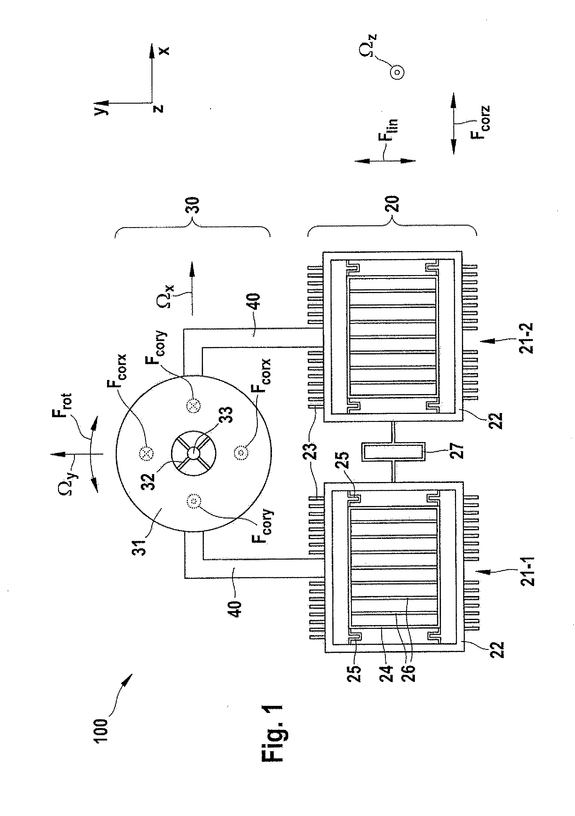
[0024]FIG. 1 is a diagram of a yaw-rate sensor 100 as per a first specific embodiment according to the present invention.

[0025]Yaw-rate sensor 100 has a first yaw-rate sensor element 20 and a second yaw-rate sensor element 30, which are coupled to one another via coupling links 40.

[0026]Yaw-rate sensor element 20 is designed as a two-mass system having two linear oscillators 21-1, 21-2. The two linear oscillators 21-1, 21-2 are mechanically coupled to one another via a spring 27. Each of two linear oscillators 21-1, 21-2 has a drive frame 22, a plurality of drive electrodes 23 being provided on each of two diametrically opposite sides of drive frame 22. A detection frame 24 which is connected to drive frame 22 via spring elements 25 is situated inside drive frame 22. It is also possible to connect detection frame 24 via a further frame, which is mounted between detection frame 24 and drive frame 22, as well as to connect corresponding spring elements to detection frame 24, in order ...

second exemplary embodiment

[0051]FIG. 5 is a diagram of a yaw-rate sensor 200 according to a second specific embodiment of the present invention. Elements which have identical construction or function as elements of the first specific embodiment are identified using identical reference numerals and are not explained in greater detail. This also applies for the following exemplary embodiments.

[0052]Yaw-rate sensor 200 as per a second specific embodiment according to the present invention has two linear oscillators 21-1, 21-2 as first yaw-rate sensor element 20 and two rotational oscillators 30-1 and 30-2 as second yaw-rate sensor elements 30. Linear oscillator 21-1 is mechanically coupled via a coupling web 40 to one rotational oscillator 30-1, and linear oscillator 21-2 is mechanically coupled via a coupling web 40 to other rotational oscillator 30-2. Coupling webs 40 are each connected at one end to one of drive frames 22 and at their other end to the circumference of particular oscillating body 31. Oscillat...

third exemplary embodiment

[0055]FIG. 6 is a diagram of a yaw-rate sensor 300 according to a third specific embodiment of the present invention.

[0056]In this yaw-rate sensor 300, a first yaw-rate sensor element 20, which has two linear oscillators 21-1, 21-2, and two rotational oscillators 30-1 and 30-2 are situated adjacent to one another in a row. Two rotational oscillators 30-1 and 30-2 are situated between linear oscillators 21-1, 21-2 and are each connected via a coupling web 40 to adjacent linear oscillators 21-1, 21-2. Rotational oscillators 30-1 and 30-2 are connected to one another via a spring element 80.

[0057]Generally the same advantages result with this specific embodiment as in the first and the second specific embodiments.


PUM


Abstract

A micromechanical yaw-rate sensor comprising a first yaw-rate sensor element, which outputs a first sensor signal, which contains information about a rotation around a first rotational axis, a second yaw-rate sensor element, which outputs a second sensor signal, which contains information about a rotation around a second rotational axis, which is perpendicular to the first rotational axis, a drive, which drives the first yaw-rate sensor element, and a coupling link, which mechanically couples the first yaw-rate sensor element and the second yaw-rate sensor element to one another, so that driving of the first yaw-rate sensor element also causes driving of the second yaw-rate sensor element.

Description

CROSS-REFERENCE[0001]The present application claims the benefit under 35 U.S.C. §119 of German Patent Application No. DE 102009027897.4 filed on Jul. 21, 2009, which is expressly incorporated herein by reference in its entirety.FIELD OF THE INVENTION[0002]The present invention relates to micromechanical yaw-rate sensors.BACKGROUND INFORMATION[0003]Micromechanical yaw-rate sensors are used in the automotive field, for example in ESP systems, for rollover sensing, or for navigation purposes. The object of the yaw-rate sensor is the correct measurement of the automobile movement around a rotational axis.[0004]A conventional micromechanical yaw-rate sensor has an oscillating body, which extends in an x-y plane and is set into a linear oscillation along a spatial axis (e.g., x-axis) lying in this plane. In the event of a rotation around a rotational axis (z-axis) which is perpendicular to the plane, the Coriolis force causes a displacement of the oscillating body in a direction (y-axis) ...

Claims


Application Information

Patent Timeline
Patent Type & Authority Applications(United States)
IPC IPC(8): G01C19/56G01C19/5712G01C19/5747
CPCG01C19/5747G01C19/5712
Inventor WREDE, MARTINCLASSEN, JOHANNESOHMS, TORSTENGECKELER, CARSTENKUHLMANN, BURKHARDFREY, JENSMEISEL, DANIEL CHRISTOPHHAUER, JOERGBALSLINK, THORSTEN
Owner ROBERT BOSCH GMBH
Why Eureka
Try Eureka