Ignition control device for use with light duty gasoline engine and method of suppressing reverse rotation of the engine

a technology of ignition control device which is applied in the direction of ignition automatic control, ignition safety means, machines/engines, etc., can solve the problems of more ropes, more time, and light-duty gasoline engine design in unidirectional rotation mode, so as to avoid further damage to other parts of the engin

Active Publication Date: 2011-02-03
ZHENGJIANG FENGLONG ELECTRIC CO LTD
View PDF7 Cites 6 Cited by
  • Summary
  • Abstract
  • Description
  • Claims
  • Application Information

AI Technical Summary

Benefits of technology

[0009]In the ignition control device according to one embodiment of the present invention, the position sensing circuit shapes the positive signal and negative signal of the second alternating current signal so as to generate the first position signal and the second position signal and provides the first position signal and the second position signal to the micro-controller; and the micro-controller judges whether the engine is in a state of reverse rotation according to the first position signal and second position signal. If the engine is in reverse rotation, micro-controller stops outputting the ignition signal so as to control the spark plug to stop igniting, which makes the engine stop due to absence of power so as to avoid further damage to other parts of the engine.
[0010]Besides, in the ignition control device according to another embodiment of the present invention, micro-controller calculates current speed of rotation for the engine on the basis of the first signal, and determines the ignition moment on the basis of the current speed of rotation for the engine to provide the electric-spark-generating control circuit with the ignition signal at the exact ignition moment so as to control the spark plug to generate electric spark for ignition of the light duty gasoline engine. Since the moment that the micro-controller outputs an ignition signal is determined according to current speed of rotation of the engine, when the rotation of the engine is at a low speed, micro-controller outputs the ignition signal just around the top dead center for the ignition of the spark plug, and when the rotation of the engine is at a high speed, micro-controller outputs the ignition signal at a certain moment ahead of top dead center for the ignition of the spark plug, which ensures that Fuel-Air Mixture in the cylinder just gets a full burn when the top dead center arrives and the consequently generated energy may push the piston to move to its furthest extent, which makes gasoline engine produce the biggest power.
[0016]By applying the method according to the above embodiment, it may be effectively judged whether the engine is in a state of reverse rotation, which helps to control the spark plug to stop igniting so as to make the engine stop due to absence of power to avoid further damage to other parts of the engine.

Problems solved by technology

But it takes time for igniter to generate an ignition signal and for Fuel-Air Mixture to be ignited and get a full burn.
Besides, light duty gasoline engine is generally designed in a unidirectional rotation mode, namely, light duty gasoline engine can only rotate in one way.
A reverse rotation of startup wheel causes that the startup rope may more and more tighter with its reverse rotation, and the startup rope may be broken to cause a damage to the startup system once tension goes too much for the startup rope.

Method used


Image

  • Ignition control device for use with light duty gasoline engine and method of suppressing reverse rotation of the engine
  • Ignition control device for use with light duty gasoline engine and method of suppressing reverse rotation of the engine
  • Ignition control device for use with light duty gasoline engine and method of suppressing reverse rotation of the engine

Examples


Embodiment Construction

[0031]Details are provided for the embodiments of the present invention as follows in conjunction with appended drawings.

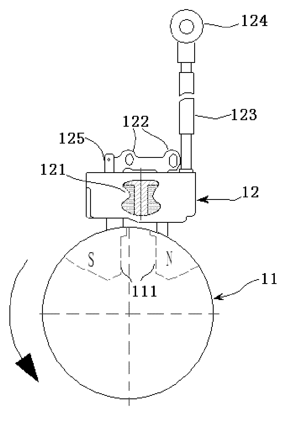
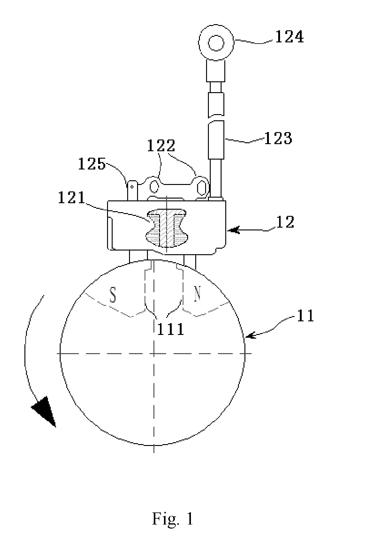
[0032]FIG. 1 is the topological diagram of an ignition assembly for a light duty gasoline engine according to an embodiment of the present invention. Without loss of generality, the ignition assembly in FIG. 1 comprises a fly wheel 11 and an igniter 12.

[0033]The fly wheel 11 is installed around the axis of engine (not shown in FIG. 1), and rotates following the rotation of the axis of the engine. The fly wheel 11 is embedded with magnetic steel 111 in its surface, and magnetic pole S and N of the magnetic steel 111 is located on the surface of the fly wheel 11.

[0034]The igniter 12 comprises a coil 121, an iron core 122, a high voltage wire 123, a high voltage cap 124, a killing tablet 125. The coil 121 is a coil group wound around the the iron core 122, which comprises a charge coil, a trigger coil, a primary ignition coil, and a secondary ignition coil (not shown...


PUM


Abstract

The invention provides an ignition control device for suppressing reverse rotation of the engine during startup process of light duty gasoline engine and a method of suppressing reverse rotation of the engine during startup process of light duty gasoline engine, the ignition control device comprises: a charge coil, a transformer, an electric-spark-generating control circuit, a trigger coil, a position sensing circuit, and a micro-controller. The position sensing circuit is used to shape the positive signal and negative signal of the second alternating current signal induced by the trigger coil while the fly wheel rotates respectively to generate a first position signal and a second position signal and provide the first position signal and the second position signal to the micro-controller. And according to the first position signal and the second position signal, it is determined by the micro-controller whether the engine is in the state of reverse rotation, and if YES, output of ignition signal is stopped to make engine halt due to absence of reverse power so as to avoid further damage to other parts of the engine. Besides, the ignition signal may be provided, according to rotation speed of the engine, by the ignition control device at the exact ignition moment to control the spark plug to generate an electric spark.

Description

FIELD OF THE INVENTION [0001]The present invention relates to the light duty gasoline engine, and particularly to the ignition control device for use with light duty gasoline engine and method of suppressing reverse rotation of the engine during startup process of the light duty gasoline engine.BACKGROUND OF THE INVENTION[0002]Gasoline Engine always needs an ignition signal from an igniter on an appropriate time point, and power is provided, by combustion of Fuel-Air Mixture in the cylinder in control, to keep gasoline engine running continuously. For light duty gasoline engine, Electronic Fuel Injection (EFI) is rarely used, whereas Ignition Advance Angle of the engine is controlled separately to implement the corresponding control functions. The moment when Fuel-Air Mixture is compressed to its possible minimum volume by Piston in the cylinder is called the Top Dead Center (TDC). In principle, it is needed to get a full burn for Fuel-Air Mixture when Top Dead Center occurs so as t...

Claims


Application Information

Patent Timeline
Patent Type & Authority Applications(United States)
IPC IPC(8): F02P5/04
CPCF02D2250/06F02P1/00F02P11/02F02P7/067
Inventor LEI, DEYOULL, JIANGZHENG, MEIJUNDONG, JIANGANG
Owner ZHENGJIANG FENGLONG ELECTRIC CO LTD
Why Eureka
Try Eureka