Control system and control method for internal combustion engine
a control system and internal combustion engine technology, applied in the direction of electric control, machines/engines, liquid fuel feeders, etc., can solve the problems of affecting the combustion state the operation of the internal combustion engine may be destabilized, and it is difficult to sufficiently reduce the egr rate using
- Summary
- Abstract
- Description
- Claims
- Application Information
AI Technical Summary
Benefits of technology
Problems solved by technology
Method used
Image

Examples
first embodiment
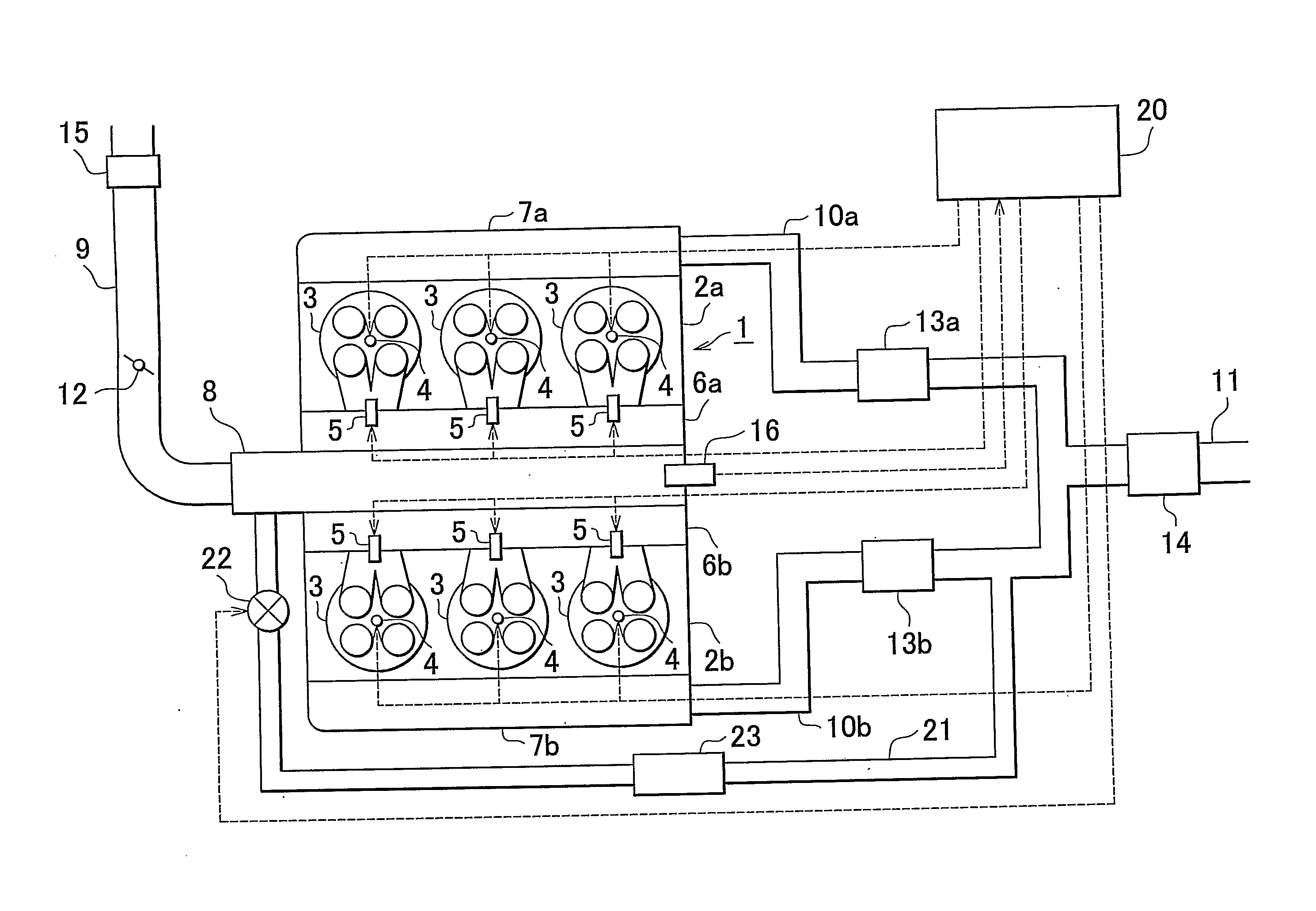
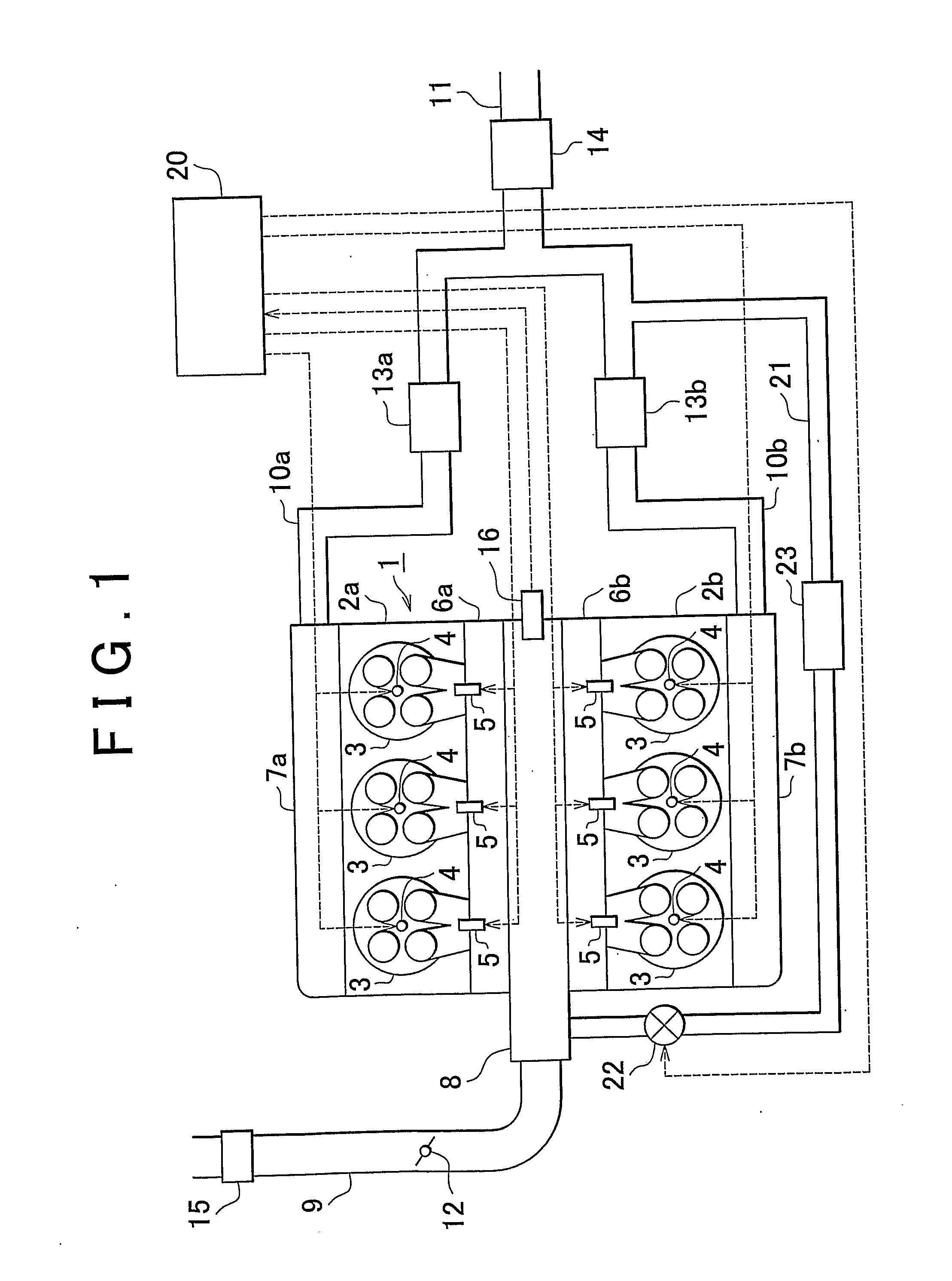
[0069]The internal combustion engine 1 is equipped with an electronic control unit (ECU) 20 that controls the internal combustion engine 1. The airflow meter 15 and the pressure sensor 16 are electrically connected to the ECU 20. Then, output signals from these components are input to the ECU 20.
[0070]The ignition plugs 4, the fuel injection valves 5, the throttle valve 12, and the EGR valve 22 are also electrically connected to the ECU 20. The ECU 20 controls these components.
[0071]As described above, in the first embodiment, one end of the EGR passage 21 is connected to the second separate exhaust passage 10b, and the other end of the EGR passage 21 is connected to the surge tank 8. Thus, exhaust gas that flows through the second separate exhaust passage 10b, that is, the exhaust gas that is discharged from the second cylinder bank 2b is introduced as EGR gas to the surge tank 8 through the EGR passage 21. Then, the EGR gas that is introduced to the surge tank 8 flows into the fi...
second embodiment
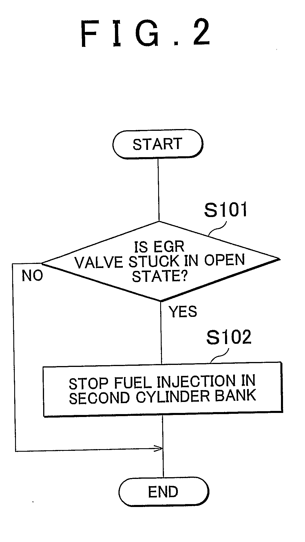
[0090]For the above reason, in the second embodiment, a delay angle is set to delay the ignition timing of each of the ignition plugs 4 in the first cylinder bank 2a when the EGR valve 22 is stuck in an open state and thus the fuel-cut control is executed in the second cylinder bank 2b.
[0091]Therefore, it is possible to prevent engine knock that is caused by the increase of the intake air in the first cylinder bank 2a.
[0092]Based on the flowchart shown in FIG. 3, description is now made on control routine that is executed when the EGR valve 22 is stuck in an open state in the second embodiment. The routine is stored in advance in the ECU 20 and executed repetitively at predetermined intervals during the operation of the internal combustion engine 1. In this routine, steps S203 to S205 are added to the routine in FIG. 2. Therefore, the steps that are also shown in FIG. 2 will no be described again.
[0093]In the routine, after the fuel-cut control is executed in the second cylinder b...
third embodiment
[0105]For the above reason, in the third embodiment, a delay angle is set to retard fuel injection timing of each of the fuel injection valves 32 in the first cylinder bank 2a when the EGR valve 22 is stuck in an open state and thus the fuel-cut control is executed in the second cylinder bank 2b.
[0106]Therefore, it is possible to prevent engine knock that may result from the increase of the amount of intake air in the first cylinder bank 2a.
[0107]Based on the flowchart shown in FIG. 5, the control routine that is executed in the third embodiment when the EGR valve 22 is stuck in an open state will now be described. The routine is stored in advance in the ECU 20 and executed repetitively at predetermined intervals during the operation of the internal combustion engine 31. The steps S102, S204, and S205 in the routine shown in FIG. 3 are respectively changed to steps S302, S304, and S305 in this routine. Therefore, the steps that are also shown in FIG. 3 will not be described again....
PUM
 Abstract
Description
Claims
Application Information
 - R&D
- Intellectual Property
- Life Sciences
- Materials
- Tech Scout
- Unparalleled Data Quality
- Higher Quality Content
- 60% Fewer Hallucinations
Browse by: Latest US Patents, China's latest patents, Technical Efficacy Thesaurus, Application Domain, Technology Topic, Popular Technical Reports.
© 2025 PatSnap. All rights reserved.Legal|Privacy policy|Modern Slavery Act Transparency Statement|Sitemap|About US| Contact US: help@patsnap.com