Method for Producing Two-Phase Stainless Steel Pipe

a technology of stainless steel pipe and two-phase, which is applied in the direction of manufacturing tools, furnaces, heat treatment equipment, etc., can solve the problem of not offering suggestions regarding the appropriate composition design, and achieve the effect of improving strength, reducing the risk of corrosion, and improving pitting resistance and crevice corrosion resistan

Active Publication Date: 2011-02-03
NIPPON STEEL CORP
View PDF5 Cites 4 Cited by
  • Summary
  • Abstract
  • Description
  • Claims
  • Application Information

AI Technical Summary

Benefits of technology

[0023]According to the present invention, a two-phase stainless steel pipe which has not only a corrosion resistance required for the oil well pipes used in deep wells or in severe corrosive environments but also has a targeted strength can be produced, without excessively adding alloying components, by selecting the cold rolling conditions.
[0038]W is an element that, similar to Mo, improves the pitting resistance and the crevice corrosion resistance, and also improves the strength through the solid-solution strengthening, and hence W can be contained if necessary. When it is intended to obtain the effect of W, W is preferably contained in a content of 0.5% or more. On the other hand, when Mo is contained excessively, the σ-phase tends to be precipitated and the toughness is deteriorated. Consequently, the content of W is preferably set at 0.5 to 6%.
[0043]N is an element that enhances the stability of austenite, and at the same time enhances the pitting resistance and the crevice corrosion resistance of the two-phase stainless steel. N, similar to C, has an effect to stabilize the austenite phase and to improve the strength, and hence N is an important element for the present invention that attains a high strength. When the content of N is less than 0.15%, no sufficient effect of N is obtained. On the other hand, when the content of N exceeds 0.35%, the toughness and the hot workability are deteriorated, and consequently, the content of N is set at 0.15 to 0.35%. For the purpose of obtaining a higher strength, the content of N preferably exceeds 0.17%. The further preferable content of N is 0.2 to 0.3%.
[0055]Also, the present invention defines the working ratio at the time of the final cold rolling. The material pipe for cold rolling is subjected to the hot working, and, if necessary, may be further subjected to a solid-solution heat treatment, and thereafter the descaling for removing the scales on the pipe surface may be performed, and thus a two-phase stainless steel pipe having an intended strength may be produced by one run of cold rolling. Alternatively, one or more runs of intermediate cold rolling (intermediate drawing) and a solid-solution heat treatment may be performed, and the final cold drawing may be performed after descaling. By performing an intermediate cold drawing, the working ratio in the final cold drawing is easily controlled, and, as compared to the case where the cold drawing is applied in the state of having been subjected to hot working, a pipe having a higher-accuracy pipe dimension can be obtained by the final cold drawing.

Problems solved by technology

However, in these documents no specific investigation has been made on the high strength attained by the cold rolling wherein the composition of the two-phase stainless steel pipe is taken into account, and no suggestion is offered with respect to the appropriate composition design or the cold rolling conditions for attaining the targeted strength, in particular, the targeted yield strength.
However, when the content of C is larger, the precipitation of the carbides tends to be excessive due to the thermal effects at the time of a heat treatment, welding or the like, and hence, from the viewpoints of the corrosion resistance and the workability of the steel, in particular, from the viewpoint of the corrosion resistance, it is necessary to reduce the content of C.

Method used


Image

  • Method for Producing Two-Phase Stainless Steel Pipe
  • Method for Producing Two-Phase Stainless Steel Pipe

Examples


example 1

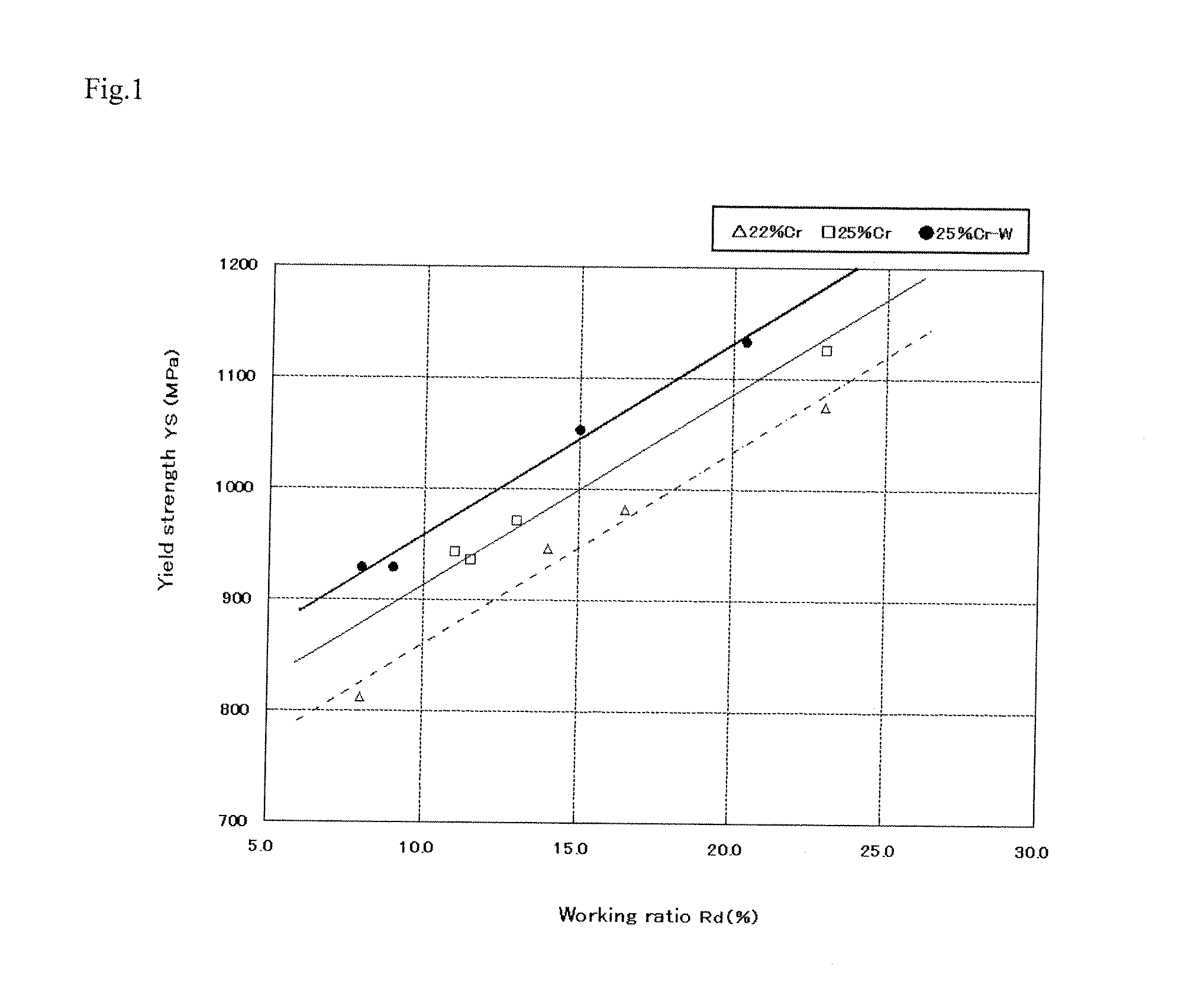
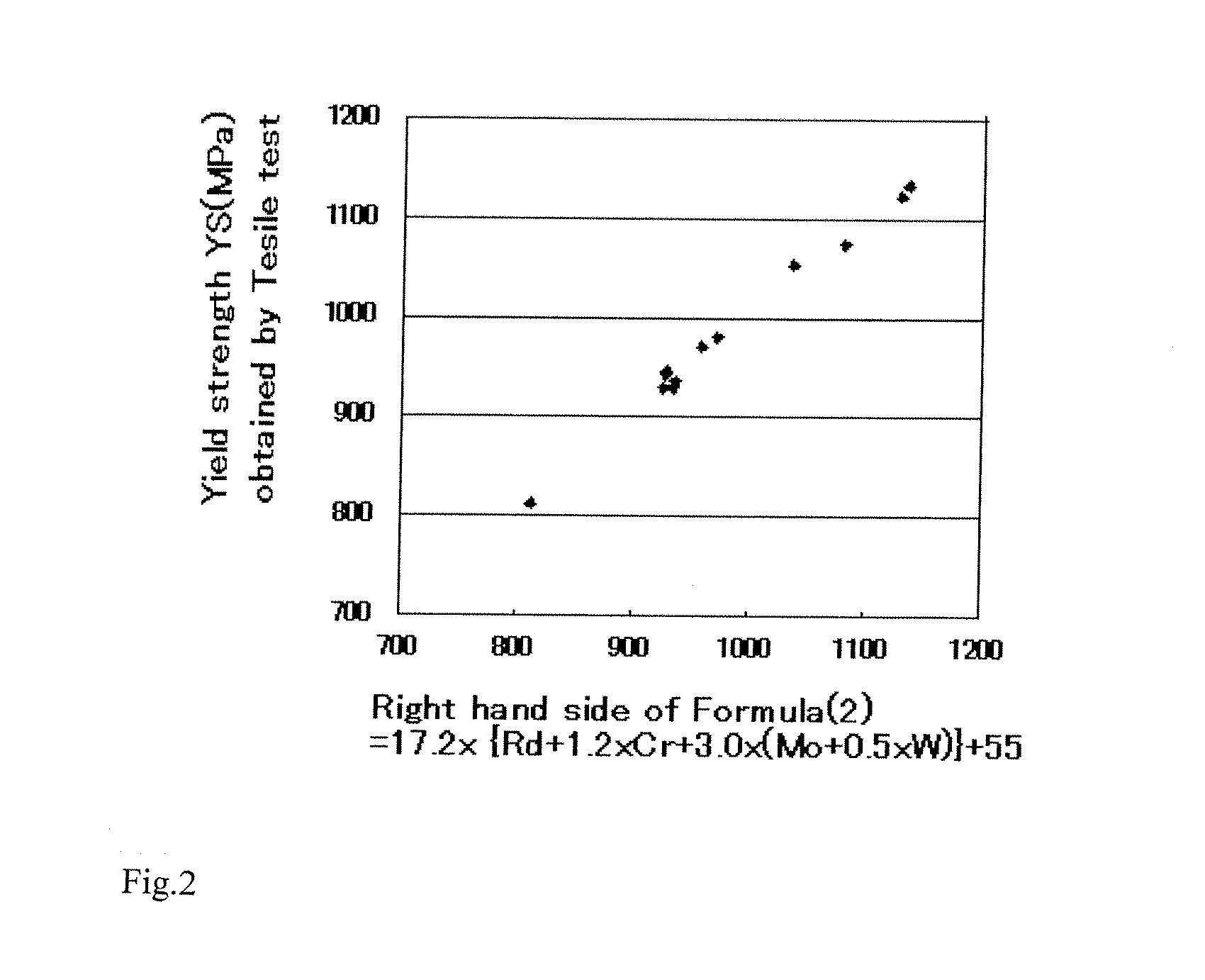
[0056]First, the two-phase stainless steels having the chemical compositions shown in Table 1 were melted with an electric furnace, and were regulated with respect to the components so as to have approximately the intended chemical compositions, and thereafter, the melting was performed by a method in which by using an AOD furnace, a decarburization treatment and a desulfurization treatment were conducted. Each of the obtained molten steels was cast into an ingot having a weight of 1500 kg and a diameter of 500 mm. Then, the ingot was cut to a length of 1000 mm to yield a billet for use in the extrusion pipe production. Next, by using this billet, a material pipe for cold drawing was formed by the hot extrusion pipe production method based on the Ugine-Sejournet method.

[0057][Table 1] Below

TABLE 1TestChemical compositions (mass %. the balance being Fe and impurities)No.CSiMnPSCrNiMoWCuN10.0140.310.490.0250.000525.156.693.082.120.480.28520.0160.330.470.0190.000524.726.553.082.130.460...


PUM

PropertyMeasurementUnit
yield stressaaaaaaaaaa
tensile strengthaaaaaaaaaa
yield strengthaaaaaaaaaa

Abstract

A two-phase stainless steel pipe that has not only a corrosion resistance required for oil well pipes but at the same time has a targeted strength is produced, without excessively adding alloying components, by selecting cold drawing conditions.
A method for producing a two-phase stainless steel pipe, which comprises, preparing a two-phase stainless steel material having a chemical composition that consists of, by mass %, C: 0.03% or less, Si: 1% or less, Mn: 0.1 to 2%, Cr: 20 to 35%, Ni: 3 to 10%, Mo: 0 to 4%, W: 0 to 6%, Cu: 0 to 3% and N: 0.15 to 0.35%, and the balance being Fe and impurities, forming a material pipe by subjecting to a hot working or further a solid-solution heat treatment, and performing a cold drawing, where the cold drawing is characterized in being performed under the conditions that the working ratio Rd, in terms of the reduction of area, in the final cold drawing step is within a range from 5 to 35%, and the following formula (1) is satisfied:
Rd(%)≧(MYS−55)/17.2−{1.2×Cr+3.0×(Mo+0.5×W)}  (1)
wherein Rd and MYS signify the working ratio (%) in terms of the reduction of area and the targeted yield strength (MPa), respectively, and Cr, Mo and W signify the contents (mass %) of the individual elements, respectively.

Description

TECHNICAL FIELD[0001]The present invention relates to a method for producing a two-phase stainless steel pipe or tube (hereinafter, collectively referred to as “pipe”) that exhibits excellent corrosion resistance even in a carbon dioxide gas corrosive environment or in a stress corrosive environment, and that has a high strength. The two-phase stainless steel pipe produced according to the present invention can be used for, for example, oil wells or gas wells (hereinafter, collectively referred to as “oil wells”).BACKGROUND ART[0002]In oil deep wells or in oil wells in severe corrosive environments involving corrosive substances such as humid carbon dioxide gas (CO2), hydrogen sulfide (H2S) or chloride ion (Cl−), austenite-ferrite two-phase stainless steel pipes having a large content of Cr such as 22Cr steel or 25Cr steel are used as oil well pipes.[0003]These austenite-ferrite two-phase stainless steels as having been subjected to the solution treatment usually applied in the prod...

Claims


Application Information

Patent Timeline
Patent Type & Authority Applications(United States)
IPC IPC(8): C21D9/08B21C1/22
CPCB21C1/003B21C1/22C21D6/004C21D6/005C21D7/02C21D8/10C22C38/40C21D2211/001C21D2211/004C21D2211/005C22C38/001C22C38/04C21D9/08C22C38/02C21D6/001C21D6/002C21D8/105C22C38/42C22C38/44
Inventor SUWABE, HITOSHI
Owner NIPPON STEEL CORP
Why Eureka
Try Eureka