Panel

a panel and panel technology, applied in the field of panels, can solve the problems of weakening the panel structure, difficult to apply rebates to metal, and generally only working well,

Inactive Publication Date: 2011-02-03
BROWNBILL DANIELLE TIFFANY
View PDF7 Cites 23 Cited by
  • Summary
  • Abstract
  • Description
  • Claims
  • Application Information

AI Technical Summary

Benefits of technology

[0014]The present invention is directed to a panel, which may at least partially overcome the abovementioned disadvantages or provide the consumer with a useful or commercial choice.

Problems solved by technology

Rebating however generally only works well with wooden constructions, metal being difficult to apply a rebate to.
Both the method of using fasteners and the provision of rebates weaken the panel structure.
Panels formed in the usual ways also tend to sag when not supported or when the panel is larger.
The weight of the members and the entire panel bears on the fasteners and the rebates and may affect the strength or integrity of the panel.
It is generally unsuitable for security situations and also tends to sag.
Wood has many disadvantages, such as being relatively heavy for a given strength, as well as splitting and breaking under impact.
Furthermore, wood will tend to rot and decay under most conditions and must be protected either by a preservative finish using an expensive chemical treatment or else painted with appropriate decorative finishes which must be reapplied periodically.
Thus the complete cost of a wooden panel is not only the original cost of erecting it, but also the continuing cost of maintenance and repair.
PVC is however generally weaker than metals.
These constructions are often riveted together and the rivets therefore offer points of weakness about which the panel may bend or be deformed.
It has also been found that panels manufactured of metal are particularly prone to rattling and creating a noise disturbance if a force is applied, for example on a windy day.

Method used


Image

  • Panel
  • Panel
  • Panel

Examples


Embodiment Construction

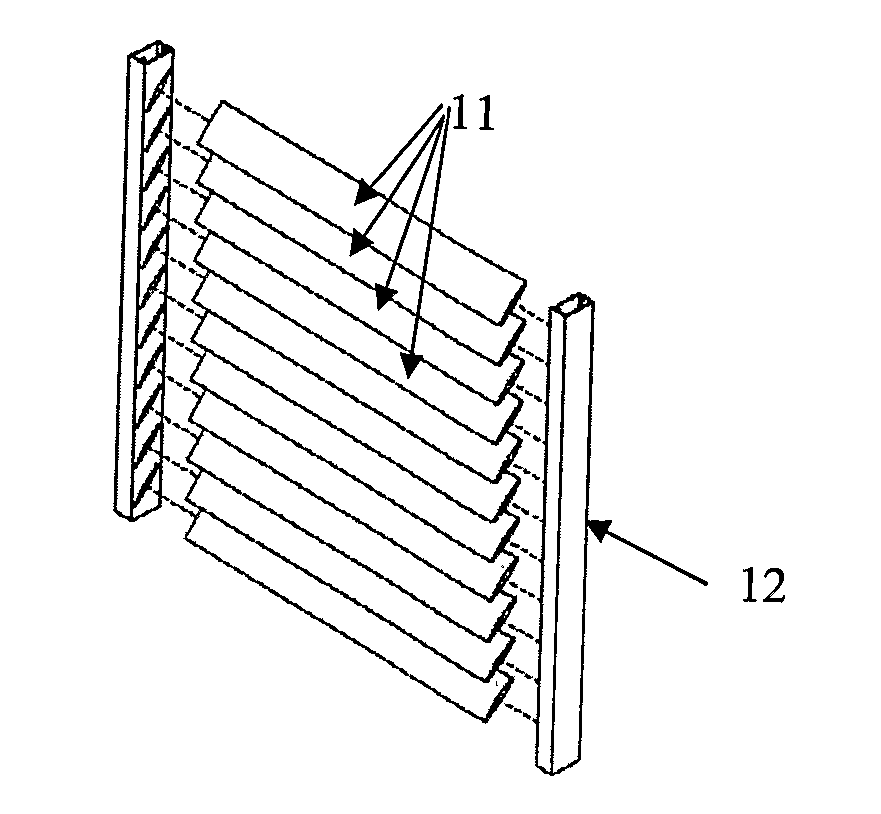
[0073]According to a preferred embodiment, a panel is provided.

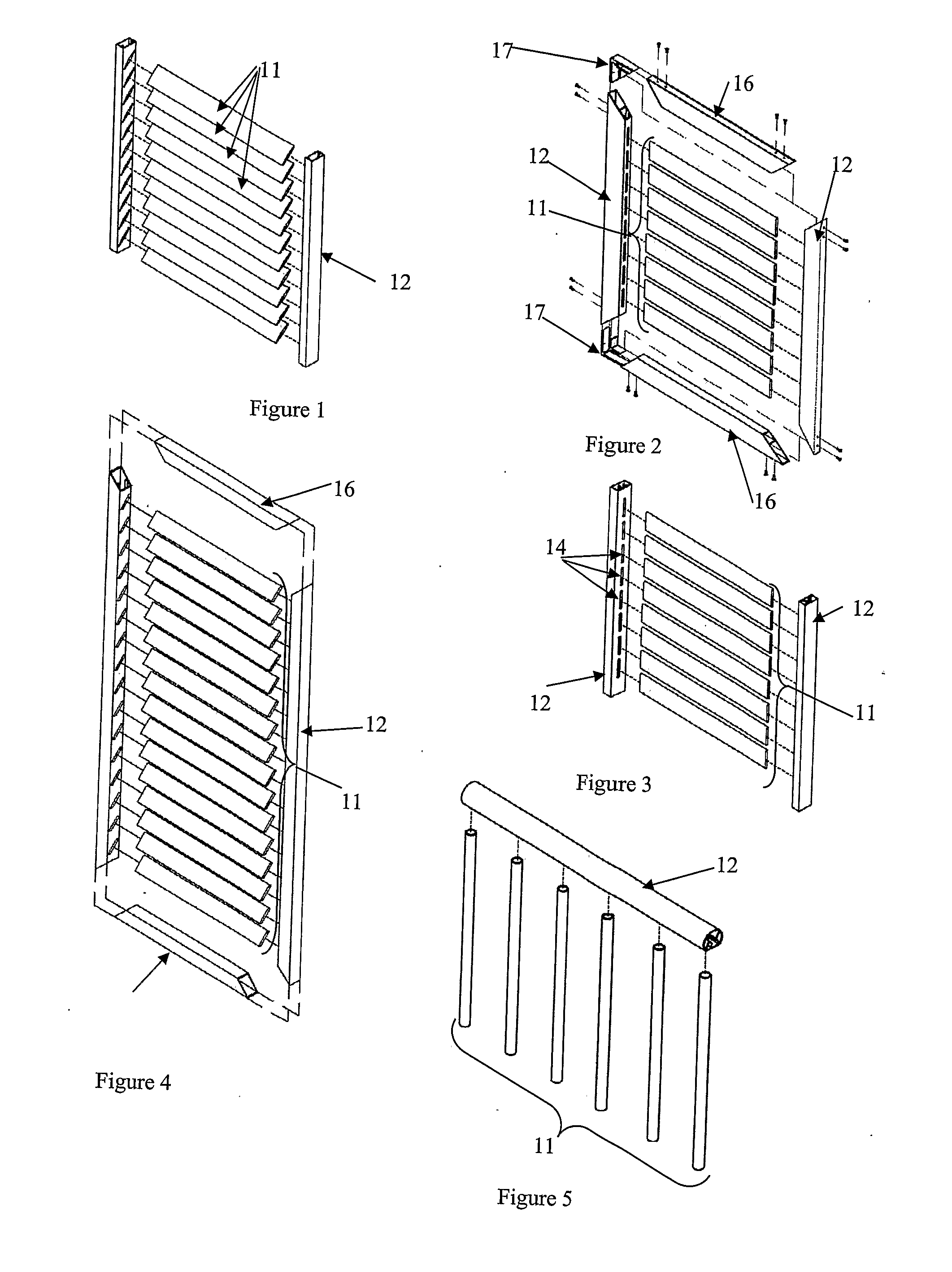
[0074]As illustrated in FIGS. 1 to 5 in particular, the panel 10 includes a plurality of first members 11 disposed in a first direction, and at least one second member 12 disposed in a second direction. The general configuration of members is illustrated in FIGS. 1 to 5 and although the first members 11 illustrated are oriented horizontally and the second members 12 vertically, it is of course anticipated that the members may be oriented in directions different to these.

[0075]The at least one second member 12 of the illustrated embodiments are hollow with a longitudinal opening 13 extending through the second member 12, a plurality of lateral openings 14 intersecting the longitudinal opening 13 to receive a portion of respective first members 11, and at least one locking member 15 provided adjacent each lateral opening 14 to abut a first member 11 forced into the lateral opening 14, to lock the first member 11 relative t...


PUM


Abstract

A panel including a plurality of first members disposed in a first direction, at least one second member disposed in a second direction provided with a longitudinal opening extending at least partially through the at least one second member; a plurality of lateral openings intersecting the longitudinal opening to receive at least a portion of respective first members, and at least one locking member provided adjacent each lateral opening to abut a first member forced into the lateral opening, to lock the first member relative to the second member.

Description

FIELD OF THE INVENTION[0001]The present invention relates to panels and attachment means for attaching one member to another and in particular to an improved style of construction for panels including lattice, screens, fencing, roofing, awnings and the like.BACKGROUND ART[0002]Panel structures are very popular and are used for many purposes. They are generally required to combine desirable characteristics of strength, light weight, and low cost. A typical fence structure for example, is formed from straight elements such as paling elements arranged in a generally vertical direction with one or more generally horizontal rail elements in a crossing pattern and fastened together, forming openings between the palings, but preventing entry or exit of anything larger than the opening dimension. A screening fence panel is typically formed from a pair at least of vertical members and a number of horizontally oriented slat members.[0003]By varying structural dimensions and relationships in t...

Claims


Application Information

Patent Timeline
Patent Type & Authority Applications(United States)
IPC IPC(8): E06B9/00
CPCE04F11/1842E06B9/01E06B7/082E04H17/168E04F11/1853E04F2011/1821
Inventor BROWNBILL, ALAN
Owner BROWNBILL DANIELLE TIFFANY
Why Eureka
Try Eureka