Battery module, battery system and electric vehicle

Inactive Publication Date: 2011-02-03
SANYO ELECTRIC CO LTD
View PDF2 Cites 39 Cited by
  • Summary
  • Abstract
  • Description
  • Claims
  • Application Information

AI Technical Summary

Benefits of technology

[0007]An object of the present invention is to provide a battery module in which a short is suffi

Problems solved by technology

However, if external stress due to vibrations or the like is continuously applied to the leads, the lead

Method used


Image

  • Battery module, battery system and electric vehicle
  • Battery module, battery system and electric vehicle
  • Battery module, battery system and electric vehicle

Examples


Example

[0067]A battery module according to a first embodiment and a battery system including the same will be described below with reference to the drawings. The battery module and the battery system according to the present embodiment are carried on an electric vehicle (e.g., an electric automobile) using electric power as a driving source.

(1) Configuration of Battery System

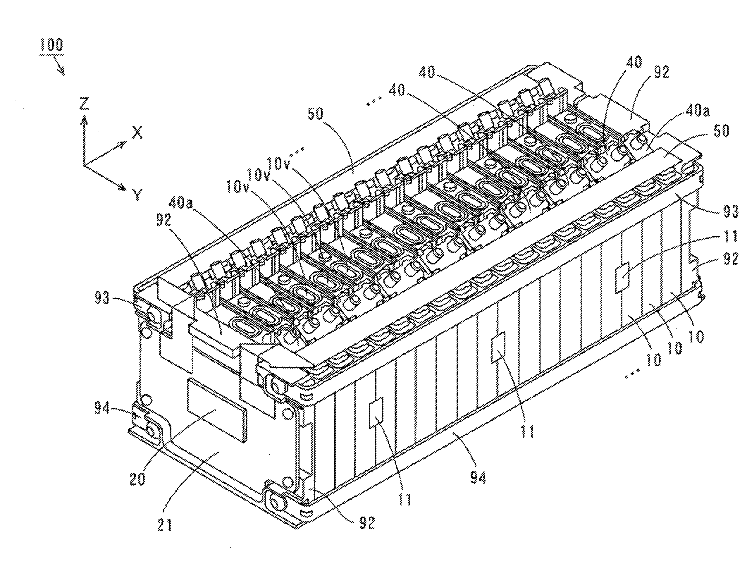
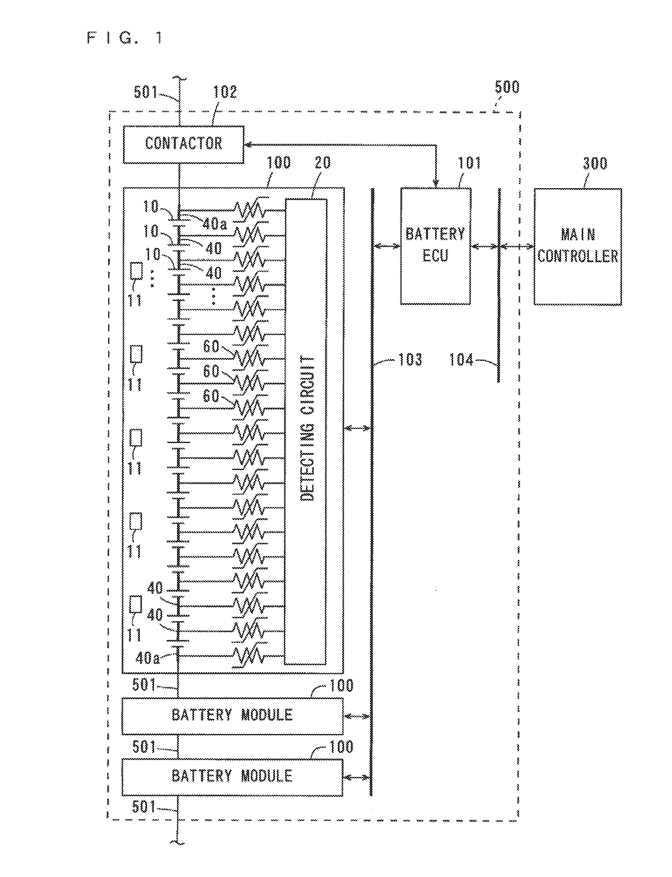
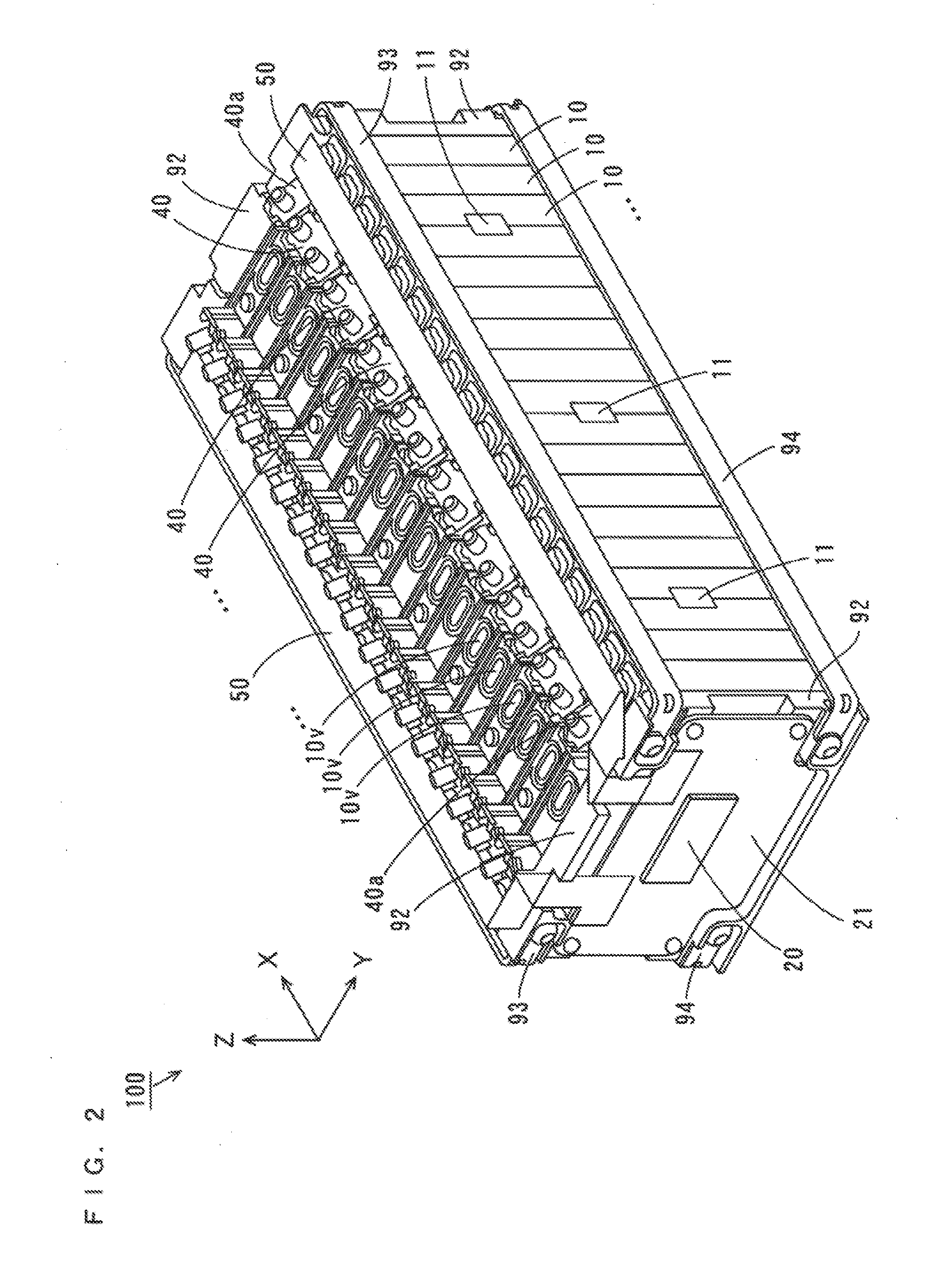
[0068]FIG. 1 is a block diagram illustrating the configuration of a battery system according to a first embodiment. As illustrated in FIG. 1, a battery system 500 includes a plurality of battery modules 100, a battery electronic control unit (ECU) 101, and a contactor 102, and is connected to a main controller 300 in an electric vehicle via a bus 104.

[0069]The battery modules 100 in the battery system 500 are connected to one another via a power supply line 501. Each of the battery modules 100 includes a plurality of (eighteen in this example) battery cells 10, a plurality of (five in this example) thermistors 11, and ...

Example

Second Embodiment

[0312]An electric vehicle according to a second embodiment will be described below. The electric vehicle according to the present embodiment includes the battery modules 100 and the battery system 500 according to the first embodiment. An electric automobile will be described below as an example of the electric vehicle.

(1) Configuration

[0313]FIG. 30 is a block diagram illustrating the configuration of an electric automobile including the battery system 500 of FIG. 1, FIG. 28 or FIG. 29. As illustrated in FIG. 30, an electric automobile 600 according to the present embodiment includes the main controller 300 and the battery system 500 illustrated in FIG. 1, a power converter 601, a motor 602, a drive wheel 603, an accelerator device 604, a brake device 605, and a rotational speed sensor 606. When the motor 602 is an alternating current (AC) motor, the power converter 601 includes an inverter circuit.

[0314]In the present embodiment, the battery system 500 is connected...


PUM


Abstract

A long-sized FPC board extending in an X-direction is connected in common to a plurality of bus bars on the side of one ends of a plurality of battery cells. Similarly, a long-sized FPC board extending in the X-direction is connected in common to a plurality of bus bars on the side of the other ends in a Y-direction of the plurality of battery cells. Each FPC board has a configuration in which a plurality of conductor lines are formed on an insulating layer, and has bending characteristics and flexibility. Each FPC board is arranged on the plurality of battery cells while being bent double.

Description

BACKGROUND OF THE INVENTION[0001]1. Field of the Invention[0002]The present invention relates to a battery module, and a battery system and an electric vehicle including the same.[0003]2. Description of the Background Art[0004]Conventionally in movable objects such as electric automobiles using electric power as driving sources, battery modules including a plurality of battery cells connected in series or in parallel have been used.[0005]In order to recognize the residual capacity (charged capacity) of the battery module or prevent overcharge and overdischarge of the battery module, a terminal voltage of the battery module is to be detected. Therefore, a detecting circuit for detecting the terminal voltage of the battery module is connected to the battery module (see, e.g., JP 8-162171 A).[0006]In the electric automobiles, the detecting circuit is generally connected to the battery module through leads composed of a metal wire, for example. However, if external stress due to vibrati...

Claims


Application Information

Patent Timeline
IPC IPC(8): B60K1/00H01M2/26
CPCB60K1/00B60K26/02Y02T10/7011H01M10/345H01M10/48H01M10/0525Y02E60/10
Inventor NISHIHARA, YOSHITOMOOHKURA, KAZUMI
Owner SANYO ELECTRIC CO LTD
Why Eureka
Try Eureka