Electrical interrupt system and method for use in a hybrid system

a hybrid system and electric interrupt technology, applied in the direction of couplings, slip couplings, electric devices, etc., can solve the problems of high voltage wires or contacts of the system

Active Publication Date: 2011-02-03
PARKER INTANGIBLES LLC
View PDF16 Cites 11 Cited by
  • Summary
  • Abstract
  • Description
  • Claims
  • Application Information

AI Technical Summary

Benefits of technology

[0004]When a portion of the electrical system is compromised for any reason, it is desirable to prevent any further use of the electric system until proper service of the system is performed. A system for preventing premature or inadvertent contact with components of an electrical system having elevated voltage levels is particularly desirable. In one aspect of the present invention, if a high voltage cable is unplugged, cut or otherwise severed, regardless the location of the high voltage cable, all high voltage connectors will open to prevent the transfer of high current discharge to the surrounding environment.

Problems solved by technology

Systems employing circuits for transmitting electrical power may pose a hazard in the event of a failure mode that results in exposing high voltage wires or contacts of the system.

Method used


Image

  • Electrical interrupt system and method for use in a hybrid system
  • Electrical interrupt system and method for use in a hybrid system
  • Electrical interrupt system and method for use in a hybrid system

Examples


Embodiment Construction

[0018]In the figures, elements having an alphanumeric designation may be referenced herein collectively or in the alternative, as will be apparent from context, by the numeric portion of the designation only. Further, the constituent parts of various elements in the figures may be designated with separate reference numerals that shall be understood to refer to that constituent part of the element and not the element as a whole. General references, along with references to spaces, surfaces, dimensions, and extents, may be designated with arrows. Furthermore, features or aspects of one figure may be incorporated in other figures.

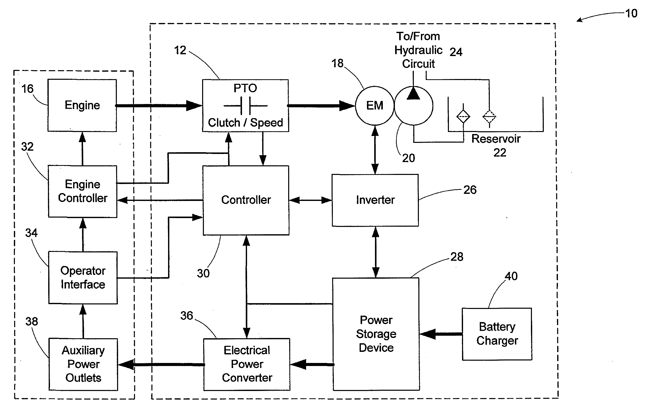
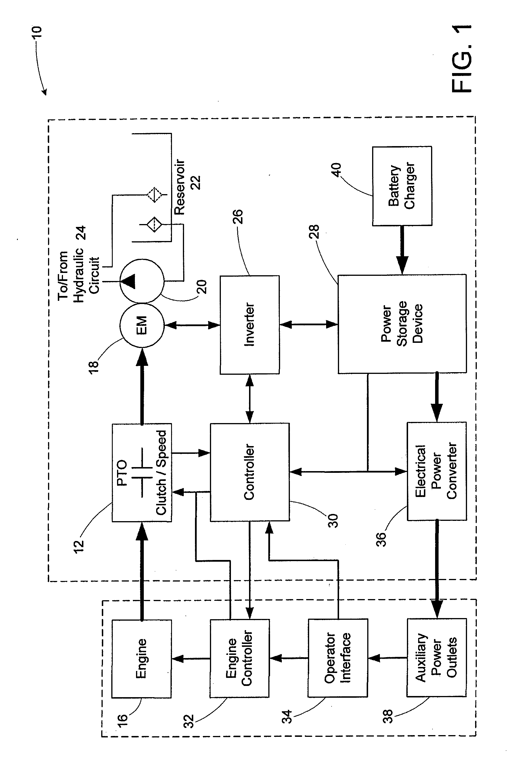
[0019]Referring now to FIG. 1, an exemplary hybrid system 10 in accordance with aspects of the present invention is illustrated. The hybrid system 10 is configured for providing hydraulic power for use in the system 10. The system 10 includes a transmission mounted power takeoff device 12. The power take off device 12 includes an actuable clutch 14. As will be...


PUM


Abstract

An electrical interlock system for including a power takeoff device operable in a first state to transfer mechanical energy from an associated combustible engine to an associated electric motor and/or generator and operative in a second state to prevent the transfer of mechanical energy from the associated combustible engine to the associated electric motor and/or generator. A relay having a first switch and an energizable portion, is coupled to the power takeoff device, the electric motor and an associated power source, such that when the energizable portion is receiving electrical power from the associated power source, the power takeoff device is in the first state and when the energizable portion is not receiving electrical power from the associated power source, the power takeoff device is in the second state.

Description

RELATED APPLICATION DATA[0001]The present application claim the benefit of the filing date of U.S. Provisional Patent Application Ser. No. 61 / 229,036 filed Jul. 28, 2009, which is incorporated herein by reference in its entirety.FIELD OF INVENTION[0002]The present invention relates to an electrical interrupt system for detecting a fault, wherein the electrical interrupt isolates electrical current and / or voltage associated with one or more direct current storage units when a fault condition is detected.BACKGROUND OF THE INVENTION[0003]Systems employing circuits for transmitting electrical power may pose a hazard in the event of a failure mode that results in exposing high voltage wires or contacts of the system. Some known systems provide high voltage interlocks that open an electrical circuit to prevent current flow. One such interlock system is described in U.S. Pat. No. 7,084,361.SUMMARY OF THE INVENTION[0004]When a portion of the electrical system is compromised for any reason, ...

Claims


Application Information

Patent Timeline
Patent Type & Authority Applications(United States)
IPC IPC(8): F16D28/00F16P3/00H02H7/06H02H7/18
CPCB60K6/387B60K6/46B60L3/04B60W10/08Y02T10/6269F16D2500/10437F16D2500/51Y02T10/6217F16D2500/1022B60W2050/0012Y02T10/62
Inventor GOMM, RALFVANDERLAAN, DALE
Owner PARKER INTANGIBLES LLC
Why Eureka
Try Eureka