Ring pixel for CMOS imagers

a cmos imager and ring pixel technology, applied in the field of imaging devices, can solve the problems of high manufacturing cost of ccds, ccd imagers suffer from a number, and ccds are susceptible to radiation damag

Active Publication Date: 2011-02-03
SRI INTERNATIONAL
View PDF29 Cites 15 Cited by
  • Summary
  • Abstract
  • Description
  • Claims
  • Application Information

AI Technical Summary

Problems solved by technology

However, CCD imagers suffer from a number of disadvantages.
For example, CCDs are susceptible to radiation damage; CCDs are often expensive to manufacture; CCDs require good light shielding to avoid image smear and; CCDs have a high power dissipation for large arrays.
CCD imagers also have a complicated driving method and a complicated fabrication process requiring a multi-phased photo process.
A control circuit, a signal processing circuit, an analog to digital (A/D) converter circuit, etc., cannot be easily i

Method used


Image

  • Ring pixel for CMOS imagers
  • Ring pixel for CMOS imagers
  • Ring pixel for CMOS imagers

Examples


Embodiment Construction

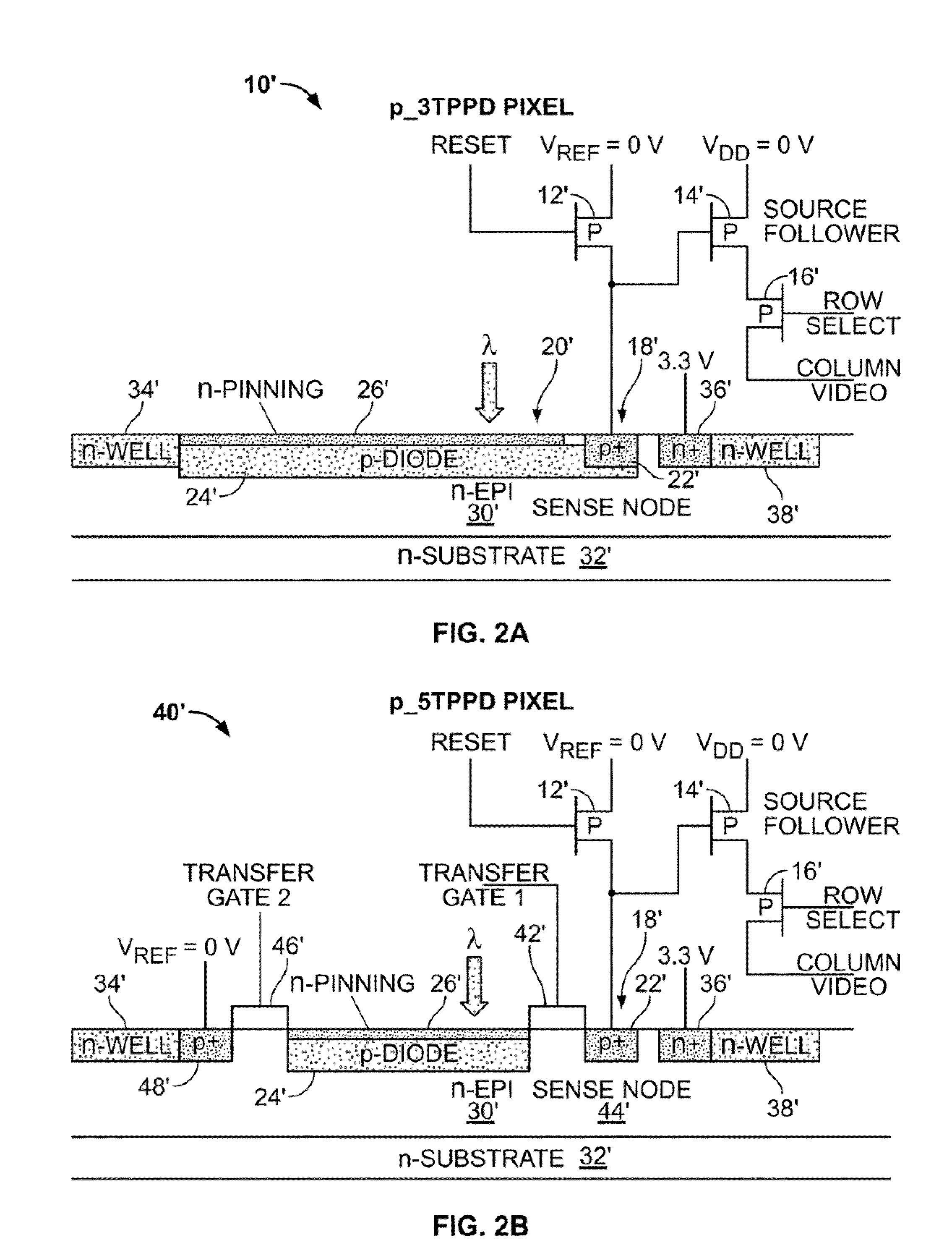
[0048]FIGS. 2A and 2B are cross-sectional views of CMOS pixels having substantially corresponding structures to the pixels of FIGS. 1A and 1B with doping conductivity types reversed, according to an embodiment of the present invention. The CMOS pixels are hereinafter designated as p—3TPPD and p—5TPPD pixels, 10′, 40′, respectively. The p—3TPPD pixel 10′ includes three PMOS transistors 12′, 14′, 16′ standing for a reset transistor 12′, a source follower transistor 14′ and a row transistor 16′. The reset transistor 12′ is electrically connected to a sense node 18′. The sense node 18′ is formed of a p+ contact 22′ and a pinned photodiode 20′. The pinned photodiode 20′ includes a thin n-type pinning layer 26′ overlying a custom p-diode implant 24′, that in turn, overlies and forms a depletion region with an n-epitaxial layer 30′. An n-substrate 32′ underlies the n-epitaxial layer 30′. An n-well 34′ is formed adjacent the pinned photodiode 20′ in the n-epitaxial layer 30′ for isolating t...


PUM


Abstract

A CMOS pixel is disclosed. The CMOS pixel includes a semiconductor substrate; a sense node formed in the semiconductor substrate and positioned substantially in the center of the CMOS pixel; a transfer gate formed about the sense node; and at least one photodiode formed about the transfer gate. A reset transistor, a source follower transistor, and a row select transistor are located substantially to one side of the CMOS pixel substantially adjacent to the photodiode. The sense node is operable to be floating. An implant may be formed about the photodiode configured to step potential in a direction toward the sense node.

Description

CROSS-REFERENCE TO RELATED APPLICATIONS[0001]This application claims the benefit of U.S. provisional patent application No. 61 / 230,440 filed Jul. 31, 2009 and U.S. provisional patent application No. 61 / 358,921 filed Jun. 27, 2010, the disclosures of which are incorporated herein by reference their entirety.FIELD OF THE INVENTION[0002]The invention relates generally to imaging devices. More specifically, the invention relates to improving the performance of CMOS imagers through a novel CMOS pixel design.BACKGROUND OF THE INVENTION[0003]Generally, an image sensor is a semiconductor device for converting an optical image into an electric signal. There are a number of different types of semiconductor-based imagers, including charge coupled devices (CCDs), photodiode arrays, charge injection devices, hybrid focal plane arrays, etc. The various types of image sensors may be broadly categorized as charge coupled devices (CCD) and complementary metal oxide semiconductor (CMOS) image sensors...

Claims


Application Information

Patent Timeline
IPC IPC(8): H01L27/146H01L31/18
CPCH01L27/14609H01L27/14658H01L27/14643H01L31/109H01L27/14689
Inventor JANESICK, JAMES ROBERT
Owner SRI INTERNATIONAL
Why Eureka
Try Eureka