
Driving circuit for an electric load and electric system comprising the circuit

a technology of driving circuit and load, applied in the direction of electric variable regulation, emergency protective arrangement for automatic disconnection, instruments, etc., can solve the problems of compromising charge, unsatisfactory prior art methods for detecting incorrect load condition, and unsatisfactory conditions

Active Publication Date: 2011-02-03
STMICROELECTRONICS SRL
View PDF17 Cites 3 Cited by
  • Summary
  • Abstract
  • Description
  • Claims
  • Application Information

AI Technical Summary

Benefits of technology

[0005]It is the object of the present invention to provide a driving circuit for an electric load, which enables a detection of the incorrectly connected load condition, that is sufficiently accurate and not detrimental in terms of circuit complexity and / or leakage. The object of the present invention is reached by a driving circuit as defined in the appended claims. It is a further object of the invention to provide an electric system comprising a load and a driving circuit.

Problems solved by technology

In such a type of driving, an undesired condition can occur, wherein the load coil is incorrectly connected to the relative driving circuit, or it even separates therefrom, compromising the charge of the battery or the load supply to the motor vehicle.
Prior art methods for detecting the incorrectly connected load condition are generally not satisfactory because of additional leakage introduced in the circuit and the circuit complexity required for their implementation.

Method used


Image

  • Driving circuit for an electric load and electric system comprising the circuit
  • Driving circuit for an electric load and electric system comprising the circuit
  • Driving circuit for an electric load and electric system comprising the circuit

Examples


Embodiment Construction

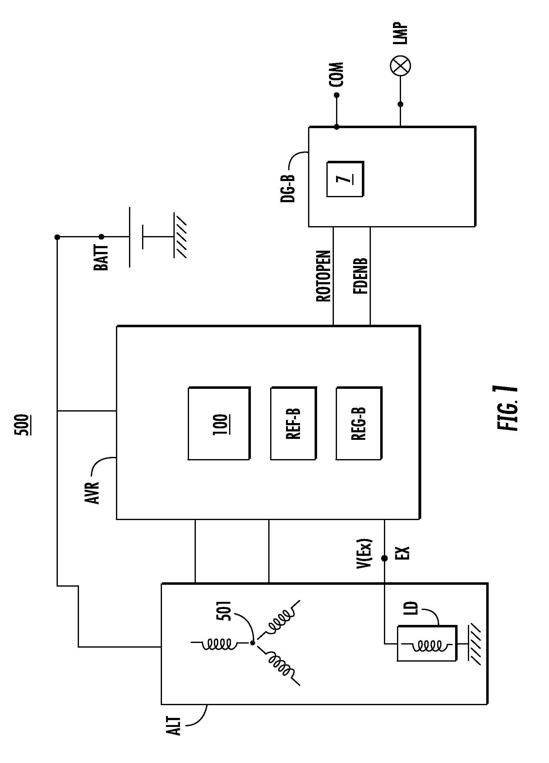
[0015]FIG. 1 schematically illustrates an example of a supply system 500, for example, for motor vehicles, which comprises an alternator ALT, an alternator voltage regulator AVR, a battery BATT, and a logic block DG-B. An electric load LD is connected at one end to the node EX of the voltage regulator AVR. The electric load LD has another end connected to a ground terminal GND.

According to an example, the load LD is a coil of an alternator rotor ALT, which is connected, by a pulley (not shown) to the motor vehicle engine. The alternator ALT includes three stator coils 501 in a tri-phase arrangement, for example.

[0016]The battery BATT is capable of providing a voltage V(BPLUS), and other electric loads of the motor vehicle can be connected thereto, such as, for example, a starter, the motor vehicle rear-window defroster resistors, a headlight, or the like. The voltage regulator AVR comprises a driving circuit 100 for the rotor coil LD, a reference-voltage generating circuit REF-G, a ...


PUM


Abstract

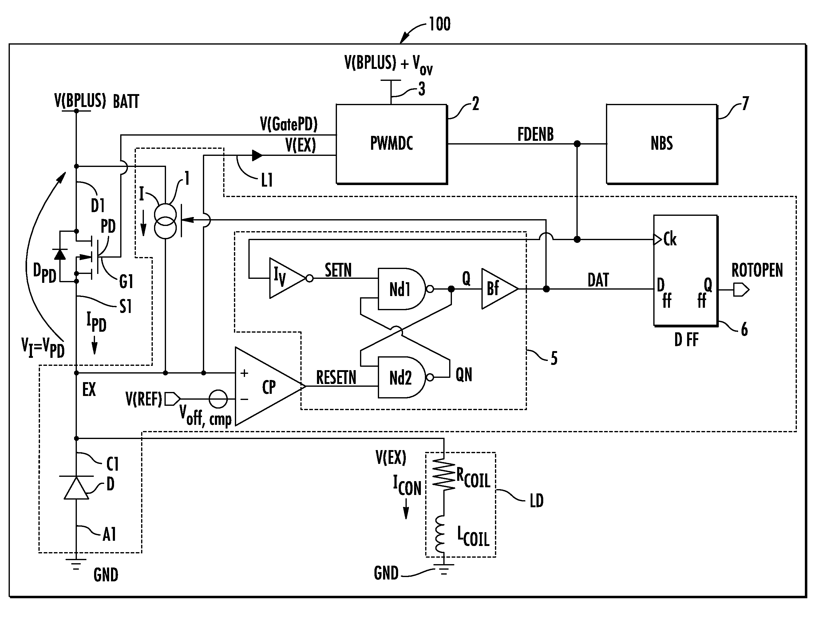
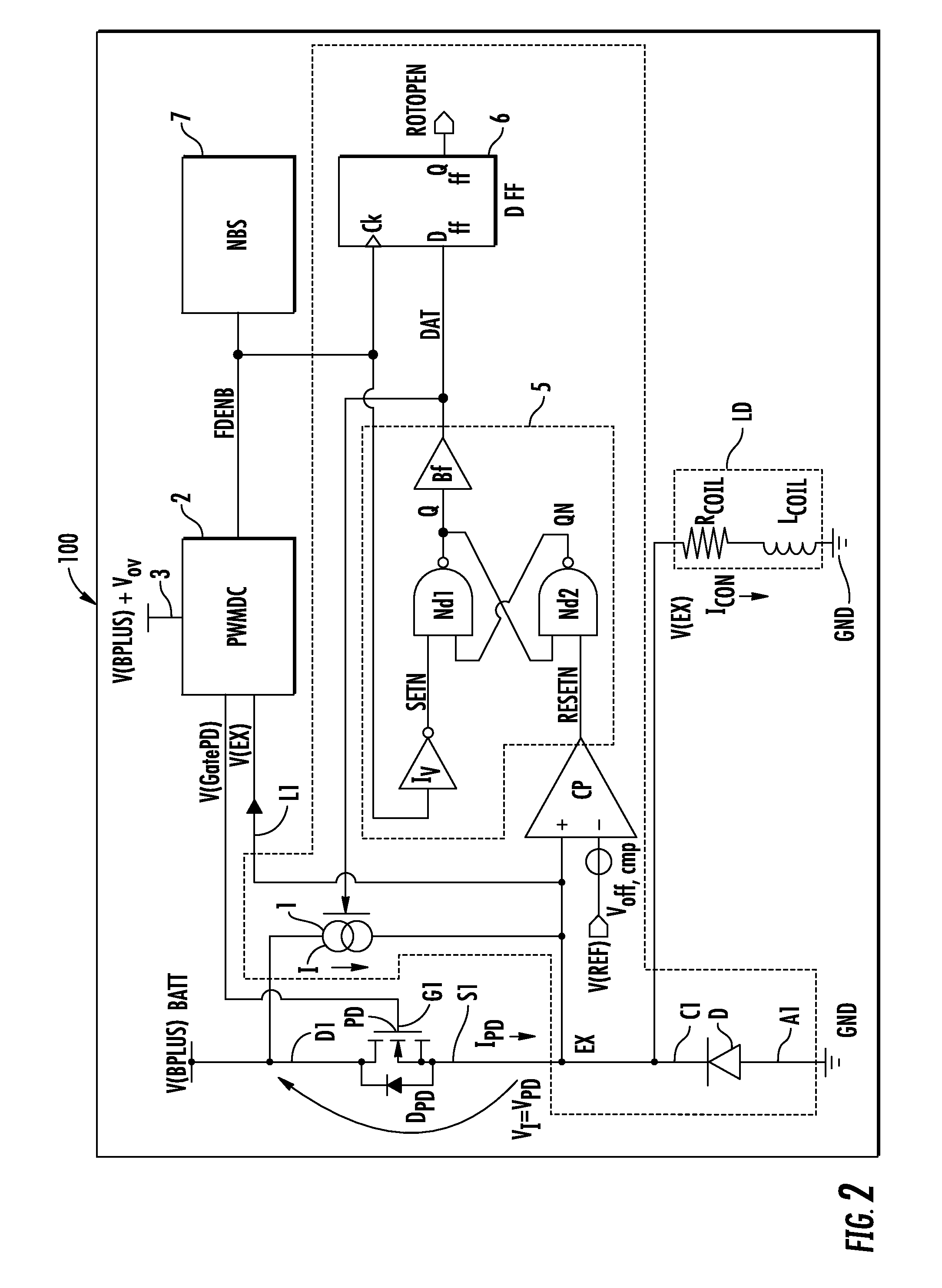
An electronic circuit includes a node coupled to a load to be driven, and a power device, which can be switched between activation and deactivation and coupled to the node. The circuit further includes a current generator having an output connected to the node and that can be enabled to generate current at least when the power device is deactivated. The circuit also includes a comparator for comparing an electric voltage of the node with a reference voltage and is configured to generate a comparison signal based thereon.

Description

FIELD OF THE INVENTION[0001]The present invention relates to a driving circuit for electric loads, such as, for example, inductive loads. In particular, the present invention relates to a method for detecting an incorrect load connection condition.BACKGROUND OF THE INVENTION[0002]Electric supply systems are known in the automotive field, which may include several components, such as, for example: alternators, voltage regulators, rectifier diode bridges, and a battery. An alternator, which converts mechanical energy into electric power, includes a rotor, equipped with a coil and three stators, equipped with other coils. The rotor coil is energized with an electric current from a power transistor, and the electric power generated by the alternator is supplied by the rectifier bridge to electric loads of the motor vehicle, or it is used to restore the charge status of the battery. In driving other inductive-type loads (for example, the throttle motor) of a motor vehicle, the use of an ...

Claims


Application Information

Patent Timeline
IPC IPC(8): G05F1/10
CPCH02H5/10H02M2003/1555H02M3/156H02H7/12H02M3/1555
Inventor AMIGHINI, MATTEOPOMA, ALBERTODI BIASE, GIUSEPPEPOLETTO, VANNI
Owner STMICROELECTRONICS SRL
Learn More