Movement detection apparatus and movement detection method

a technology of movement detection and detection apparatus, applied in the direction of acceleration measurement using interia force, instruments, television systems, etc., can solve the problems of false detection of shaking direction different from the user's intention, sensor operation error, etc., to reduce false detection of acceleration and reduce erroneous operation of devices.

Inactive Publication Date: 2011-02-03
CANON KK
View PDF24 Cites 46 Cited by
  • Summary
  • Abstract
  • Description
  • Claims
  • Application Information

AI Technical Summary

Benefits of technology

[0007]The present invention has been conceived in view of the above problems, and the present invention realizes an acceleration detection technique capable of reducing false detections of accelerations generated by user's unintended movements and reducing erroneous operations of device caused by the false detections.
[0014]According to the present invention, false detections of accelerations generated by user's unintended movements and erroneous operations of device caused by the false detections can be reduced.

Problems solved by technology

However, when the acceleration sensor is used as input means for executing a predetermined function in accordance with an intentional shaking movement of the user, an acceleration generated by an unintended movement of the user, such as putting down the device on a desk or picking up the device, may be detected, and the sensor may be erroneously operated.
However, a shaking direction different from the user's intention may be falsely detected in the method.

Method used


Image

  • Movement detection apparatus and movement detection method
  • Movement detection apparatus and movement detection method
  • Movement detection apparatus and movement detection method

Examples


first embodiment

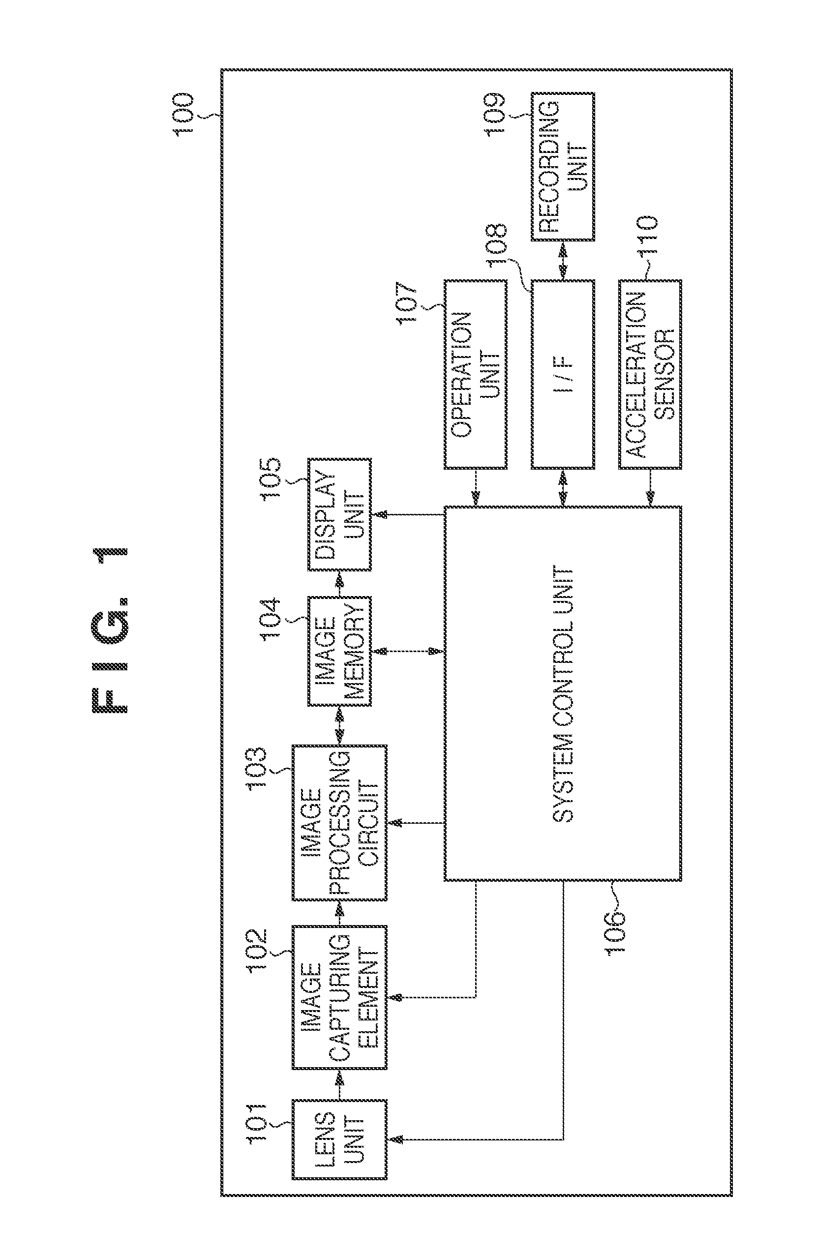
[0025]A configuration of an electronic device of a first embodiment will be described first with reference to FIGS. 1 to 5. In FIG. 1, reference numeral 100 denotes an image capturing apparatus such as a digital camera. In the present embodiment, the image capturing apparatus 100 is a portable image capturing apparatus such as a compact digital camera. Reference numeral 101 denotes a lens unit comprising a zoom lens for adjusting the focal distance to change the angle of view, an aperture shutter for adjusting the light quantity to realize an exposure function, a focus lens for adjusting the focus, etc. The light passing through the lens unit 101 is received by an image capturing element 102, such as a CCD and a CMOS, and converted from a light signal to an electric signal. The photoelectrically converted electric signal is further input into an image processing circuit 103, a pixel interpolation process or a color conversion process is applied to the signal, and the signal is trans...

second embodiment

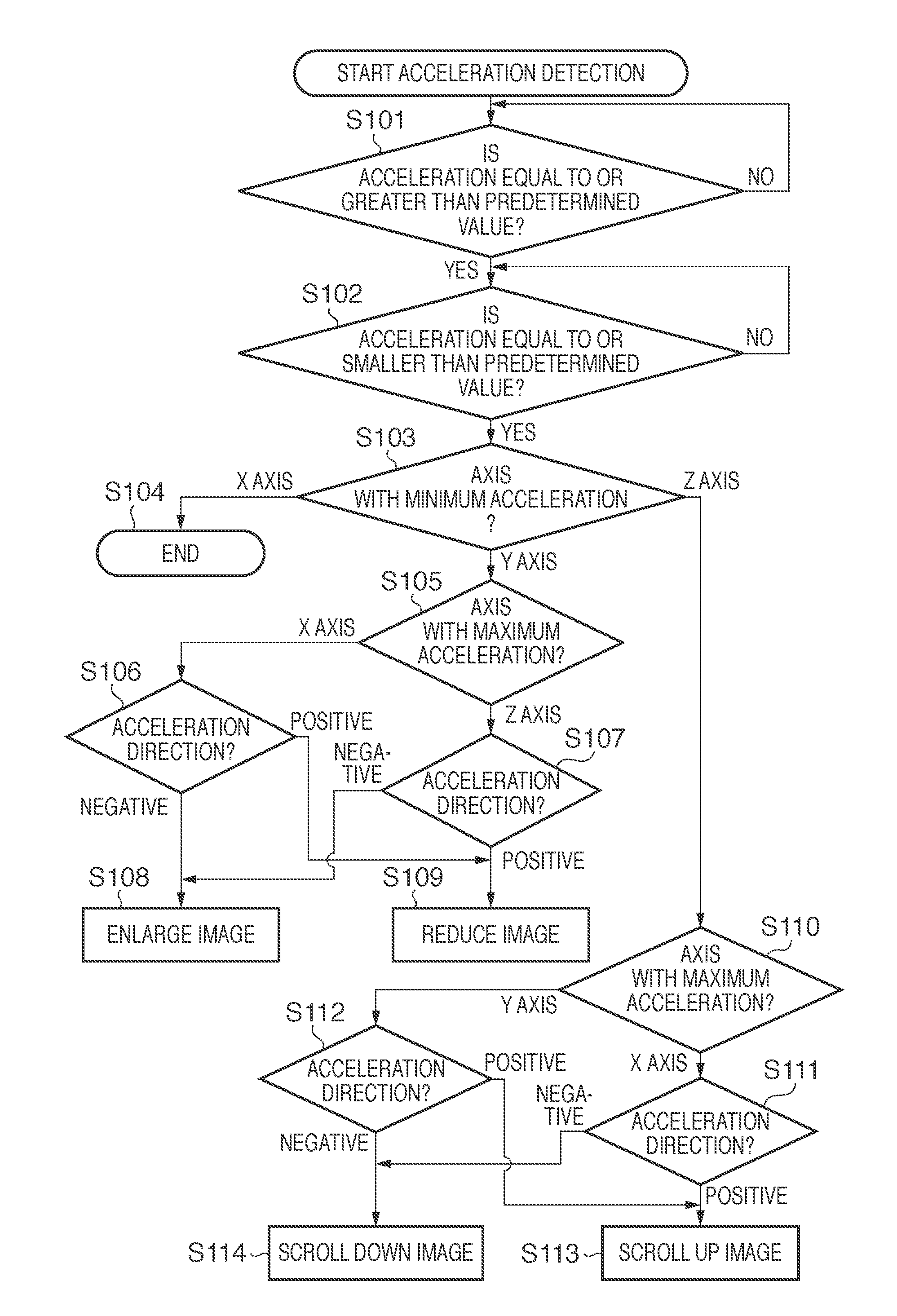
[0046]An acceleration detection process of a second embodiment will be described below with reference to FIG. 6. In the example of the present embodiment, a shaking movement of the image capturing apparatus 100 is determined by an axis with minimum acceleration and the number of changes. Two types of slide show functions are allocated depending on the shaking movement in the back and forth direction and the number of movements, and two types of rotation functions of displayed image are allocated depending on the shaking movement in the up and down direction and the number of movements.

[0047]Steps S201 to S204 of FIG. 6 are the same as the process of steps S101 to S104 of FIG. 5, and the description will not be repeated. More specifically, in FIG. 6, if the rotational axis is the Y axis in step S203, that is in the rotational motion of the Z-X plane, the process moves to step S205. The computing unit 202 executes a counting computation process of counting the number of changes in the...

third embodiment

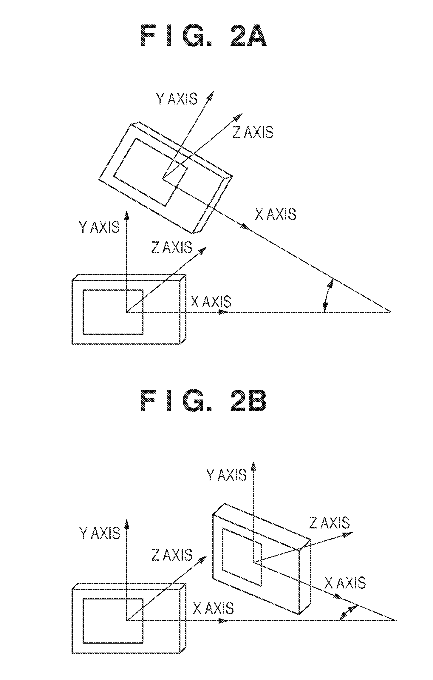
[0050]A case in which a cell phone is the detection object will be described with reference to FIGS. 7A and 7B. In FIGS. 7A and 7B, as for the axis directions of the acceleration sensor 110 that detects a shaking movement of the cell phone, the left and right direction (horizontal direction) is defined as the X axis, the up and down direction (perpendicular direction) is defined as the Y axis, and the back and forth direction is defined as the Z axis. The cell phone is often vertically long in normal usage. The display unit 105 is arranged on the upper side with respect to the center, and the operation unit 107 is arranged on the lower side. The cell phone is configured to be operated by holding the lower side.

[0051]When a shaking movement of the cell phone is performed in the left and right direction, a rotational motion in the X-Y plane is made as shown in FIG. 7A. When a shaking movement is performed in the back and forth direction, a rotational motion in the Y-Z plane is made as...


PUM


Abstract

A movement detection apparatus that detects a shake added by an operator to execute a function of a device, the apparatus comprises an acceleration detection unit configured to detect accelerations caused by a shake in at least three-axis directions; a determination unit configured to determine an axis with a minimum value of acceleration and an axis with a maximum value of acceleration among the accelerations in at least three-axis directions detected by the acceleration detection unit; a decision unit configured to decide a direction of the shake added by the operator based on the axis with the minimum value and the axis with the maximum value determined by the determination unit; and a selection unit configured to select a predetermined function based on the result of the decision unit.

Description

BACKGROUND OF THE INVENTION[0001]1. Field of the Invention[0002]The present invention relates to a technique of detecting an acceleration when the orientation of an object changes and executing a function of a device in accordance with the detected acceleration.[0003]2. Description of the Related Art[0004]An example of a conventional acceleration detection apparatus includes an acceleration sensor using, for example, means for detecting a change in the electrostatic capacity generated between a movable electrode and a fixed electrode of a sensor based on an acceleration added to an object. In recent years, a three-axis acceleration sensor capable of detecting an acceleration added in any direction of a three-dimensional space by one sensor has been developed. The three-axis acceleration sensor is mounted on a compact digital camera, a cell phone, etc. and can detect a gravity acceleration in the direction of gravitational force when the device is still to detect the orientation and ...

Claims


Application Information

Patent Timeline
Patent Type & Authority Applications(United States)
IPC IPC(8): H04N5/222G06F3/01G01P15/18G03B17/00G03B17/02G03B17/18H04N5/232
CPCG06F1/1694H04N5/23258G06F3/017H04N23/6812
Inventor TSUBUSAKI, AKIHIRO
Owner CANON KK
Why Eureka
Try Eureka