Ball roller bearing and method for the installation of such a ball roller bearing

a ball roller bearing and roller bearing technology, applied in the field of ball roller bearings, can solve the problems of comparatively small increase in and achieve the effect of improving the radial load bearing capacity of the ball roller bearings

Inactive Publication Date: 2011-02-03
SCHAEFFLER TECH AG & CO KG
View PDF6 Cites 14 Cited by
  • Summary
  • Abstract
  • Description
  • Claims
  • Application Information

AI Technical Summary

Benefits of technology

[0010]The invention is thus based on the realization that it is possible in a simple and economical manner with a bearing cage designed in this way to create the conditions for enabling a ball roller bearing with similar raceway dimensions to those of a comparable deep groove ball bearing to be filled with a significantly higher number of ball rollers and, as a result, to be designed in particular with a higher radial load bearing capacity and with a significantly increased life.
[0025]As a concluding seventh assembly step, the cage rims of the bearing cage are then flanged in the direction of the side faces of the ball rollers in order in this way to provide the already described axial guidance for the ball rollers for the purpose of avoiding the transverse wobbling effect described in certain operating states, and optional greasing and / or sealing of the ball roller bearing as required or not required by the specific use.

Problems solved by technology

Thus, although it was possible to reduce the axial installation space and the weight of the ball roller bearing and increase the axial loading capacity thereof in comparison with conventional deep groove ball bearings, the increase in the radial load bearing capacity of the ball roller bearing was however comparatively small.

Method used


Image

  • Ball roller bearing and method for the installation of such a ball roller bearing
  • Ball roller bearing and method for the installation of such a ball roller bearing
  • Ball roller bearing and method for the installation of such a ball roller bearing

Examples


first embodiment

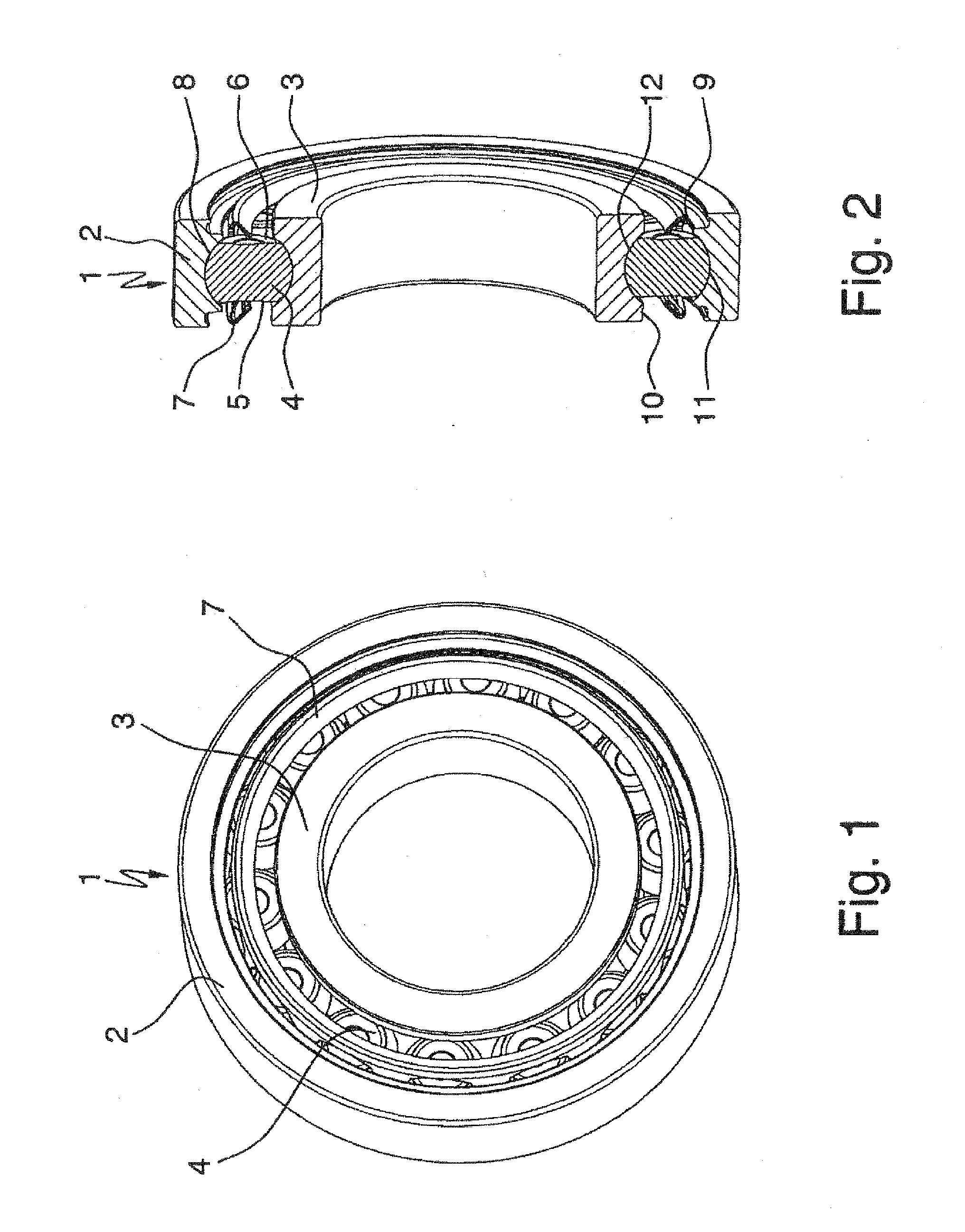
[0027]FIG. 1 shows an enlarged three-dimensional representation of a plan view of a ball roller bearing designed in accordance with the invention;

[0028]FIG. 2 shows a three-dimensional cross section through the first embodiment of the ball roller bearing shown in FIG. 1 and designed in accordance with the invention;

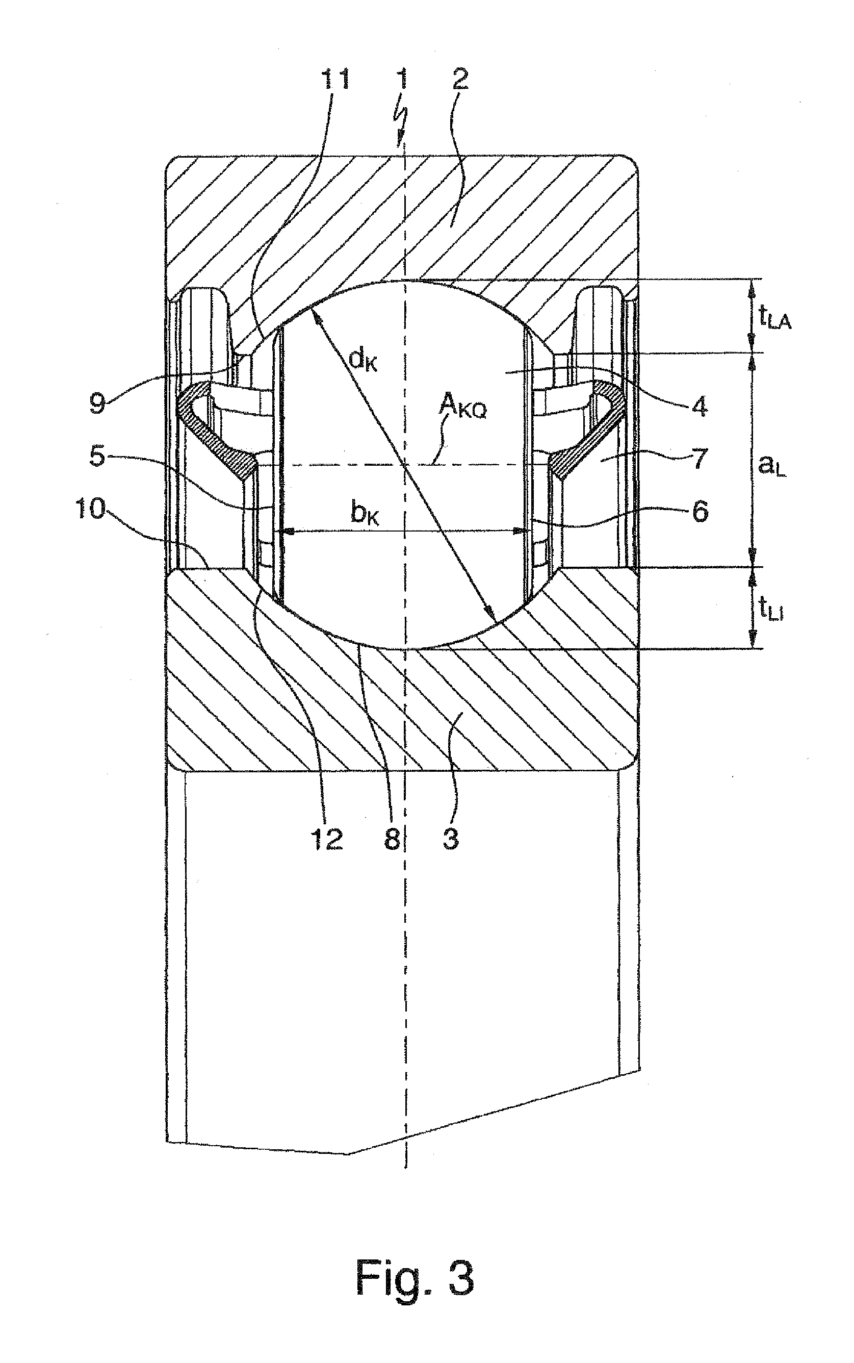
[0029]FIG. 3 shows an enlarged representation of the upper half of the cross section through the first embodiment of the ball roller bearing according to the invention shown in FIG. 2;

second embodiment

[0030]FIG. 4 shows an enlarged representation of the upper half of the cross section through a ball roller bearing according to the invention;

[0031]FIG. 5 shows a three-dimensional overall representation of the bearing cage of the embodiments shown in FIGS. 3 and 4 of a ball roller bearing designed in accordance with the invention;

[0032]FIG. 6 shows an enlarged representation of a cage pocket of the bearing cage of the embodiments shown in FIGS. 3 and 4 of a ball roller bearing designed in accordance with the invention;

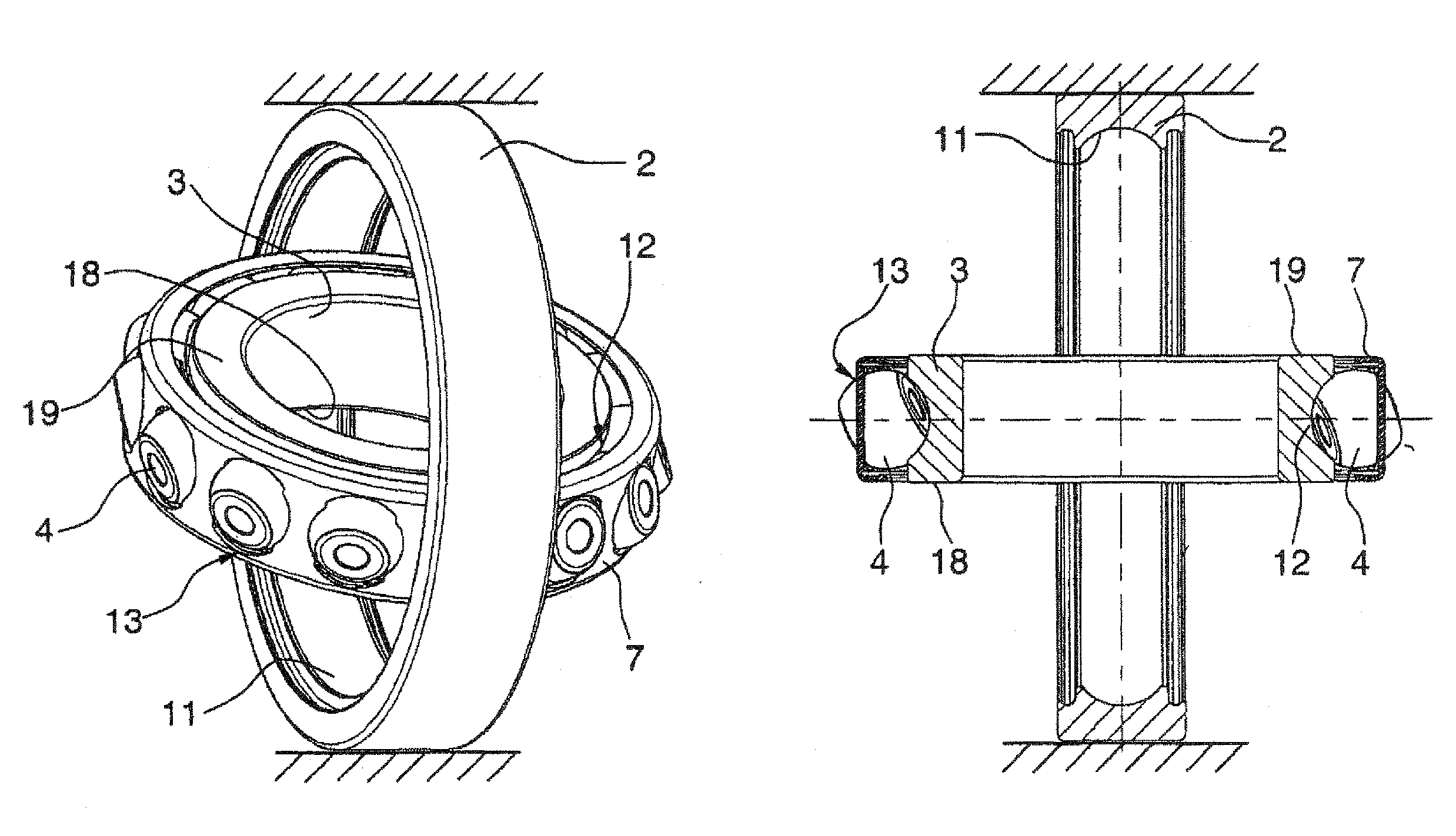
[0033]FIG. 7 shows a three-dimensional view and a cross section through the first embodiment of a ball roller bearing according to the invention after the first method step for the assembly thereof;

[0034]FIG. 8 shows a three-dimensional view and a cross section through the first embodiment of a ball roller bearing according to the invention after the second method step for the assembly thereof;

[0035]FIG. 9 shows a three-dimensional view and a cross section through the...


PUM

PropertyMeasurementUnit
pressure angleaaaaaaaaaa
widthaaaaaaaaaa
diameteraaaaaaaaaa

Abstract

A ball roller bearing and to a method for the installation thereof. The ball roller bearing has an outer bearing race, and an inner bearing race, and a plurality of ball rollers, which are disposed between the bearing races and are held at equal distances to each other by a bearing cage. For this purpose, the ball rollers have a width of approximately 70% of the diameter of a spherical shape thereof, and roll with bearing surfaces thereof in two groove-shaped raceways, the depth of which is smaller than the distance between the outer and inner bearing race. The cage pockets of the bearing cage have a cross-sectional contour of a ball roller disposed in the longitudinal and transverse directions to the circumferential direction. The method for installation of the ball roller bearing is a cross / oblique pivot mount between the inner and outer bearing races and the ball rollers.

Description

FIELD OF THE INVENTION[0001]The invention relates to a ball roller bearing having the features of the preamble of patent claim 1 and to a method for assembling such a ball roller bearing, which can be used with particular advantage as a fixed bearing for the input and output shaft of a motor vehicle shift transmission, for example.BACKGROUND OF THE INVENTION[0002]It is a matter of common knowledge in the engineering of rolling bearings that deep groove ball bearings are rigid radial rolling bearings which cannot be disassembled, are distinguished especially by equally high radial and axial load bearing capacity and, owing to the low friction thereof, have the highest rotational speed limits of all bearings. These deep groove ball bearings consist essentially of an outer bearing race, an inner bearing race and a number of balls, disposed between the bearing races, as rolling elements which roll on groove-shaped ball raceways machined into the inside of the outer bearing race and into...

Claims


Application Information

Patent Timeline
Patent Type & Authority Applications(United States)
IPC IPC(8): F16C19/49B23P11/00
CPCF16C33/36F16C33/467Y10T29/4968F16C43/06F16C2361/61F16C33/545F16C19/26
Inventor DOEPPLING, HORSTGEIGER, ERNSTHOFMANN, HEINRICHWIRTH, WERNER
Owner SCHAEFFLER TECH AG & CO KG
Why Eureka
Try Eureka