
Open center hydraulic system

Active Publication Date: 2011-02-10
CNH IND AMERICA LLC
View PDF11 Cites 4 Cited by
  • Summary
  • Abstract
  • Description
  • Claims
  • Application Information

AI Technical Summary

Benefits of technology

[0003]One way to increase the craning and breakout specifications on the work vehicle, such as a loader-backhoe, would be to increase the operating pressure of the hydraulic system. However, increasing the operating pressure poses a number of problems. First, the vehicle structure may not be able to withstand dynamic loads that may be encountered during operation at an increased hydraulic pressure and full operating speed. Second, maintaining an increased operating pressure would require increased power requirements if the flow of hydraulic fluid remains constant. In each instance, an increase in weight and power results in increased cost of the vehicle.
[0004]What is needed is a hydraulic system having a “boost” mode that provides additional lifting or breakout forces by virtue of selectively increased hydraulic pressure, i.e., selected as needed by the vehicle operator, with the system simultaneously operating at a reduced flow rate of hydraulic fluid. The reduced flow rate of hydraulic fluid would result in slower movement of the vehicle components, similarly reducing the dynamic loads and also reducing the power requirements associated with operation of the vehicle.SUMMARY OF THE INVENTION

Problems solved by technology

However, increasing the operating pressure poses a number of problems.
First, the vehicle structure may not be able to withstand dynamic loads that may be encountered during operation at an increased hydraulic pressure and full operating speed.
Second, maintaining an increased operating pressure would require increased power requirements if the flow of hydraulic fluid remains constant.
In each instance, an increase in weight and power results in increased cost of the vehicle.
The reduced flow rate of hydraulic fluid would result in slower movement of the vehicle components, similarly reducing the dynamic loads and also reducing the power requirements associated with operation of the vehicle.

Method used


Image

  • Open center hydraulic system
  • Open center hydraulic system
  • Open center hydraulic system

Examples


Embodiment Construction

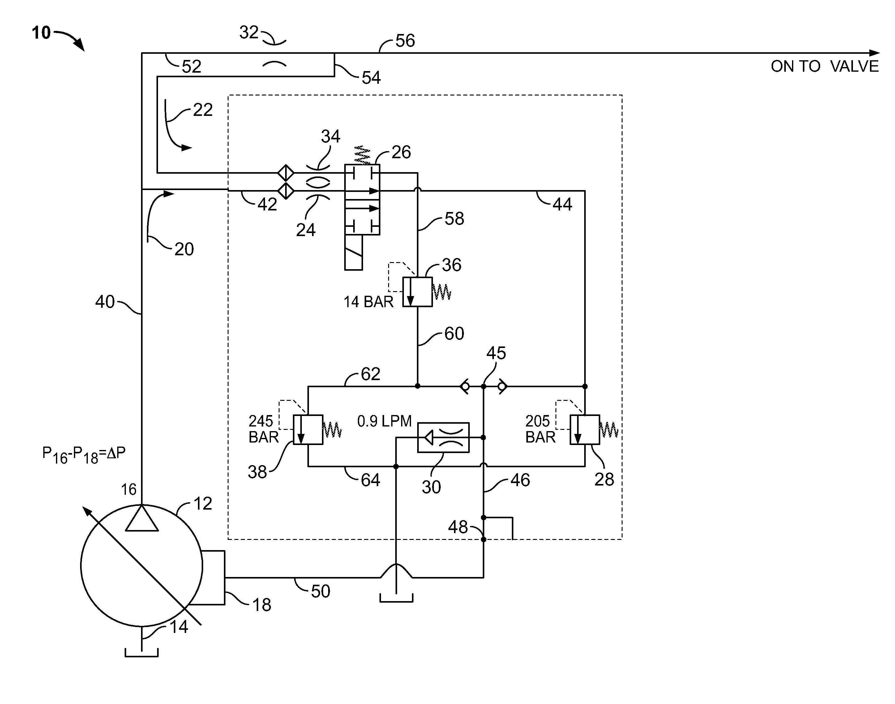
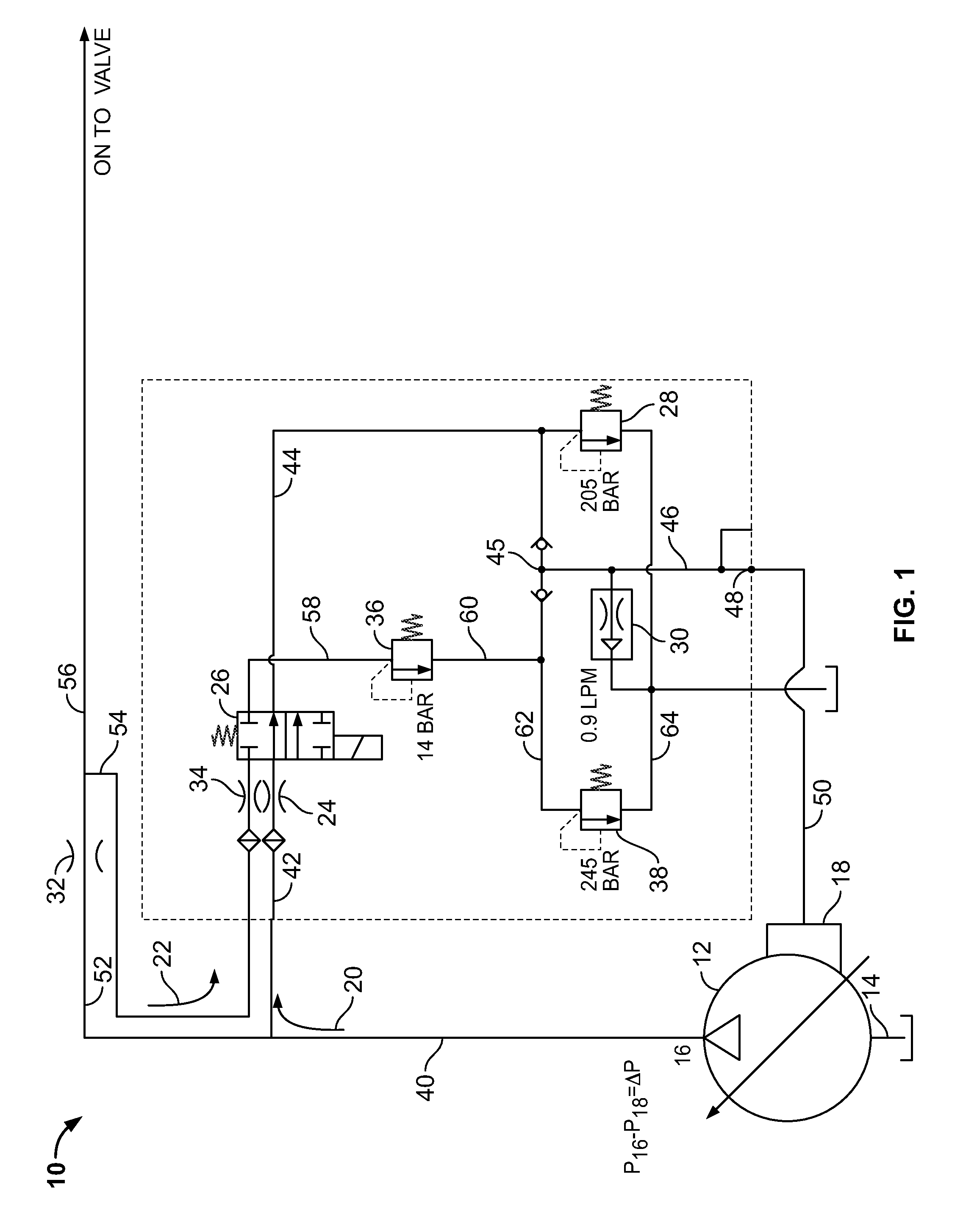
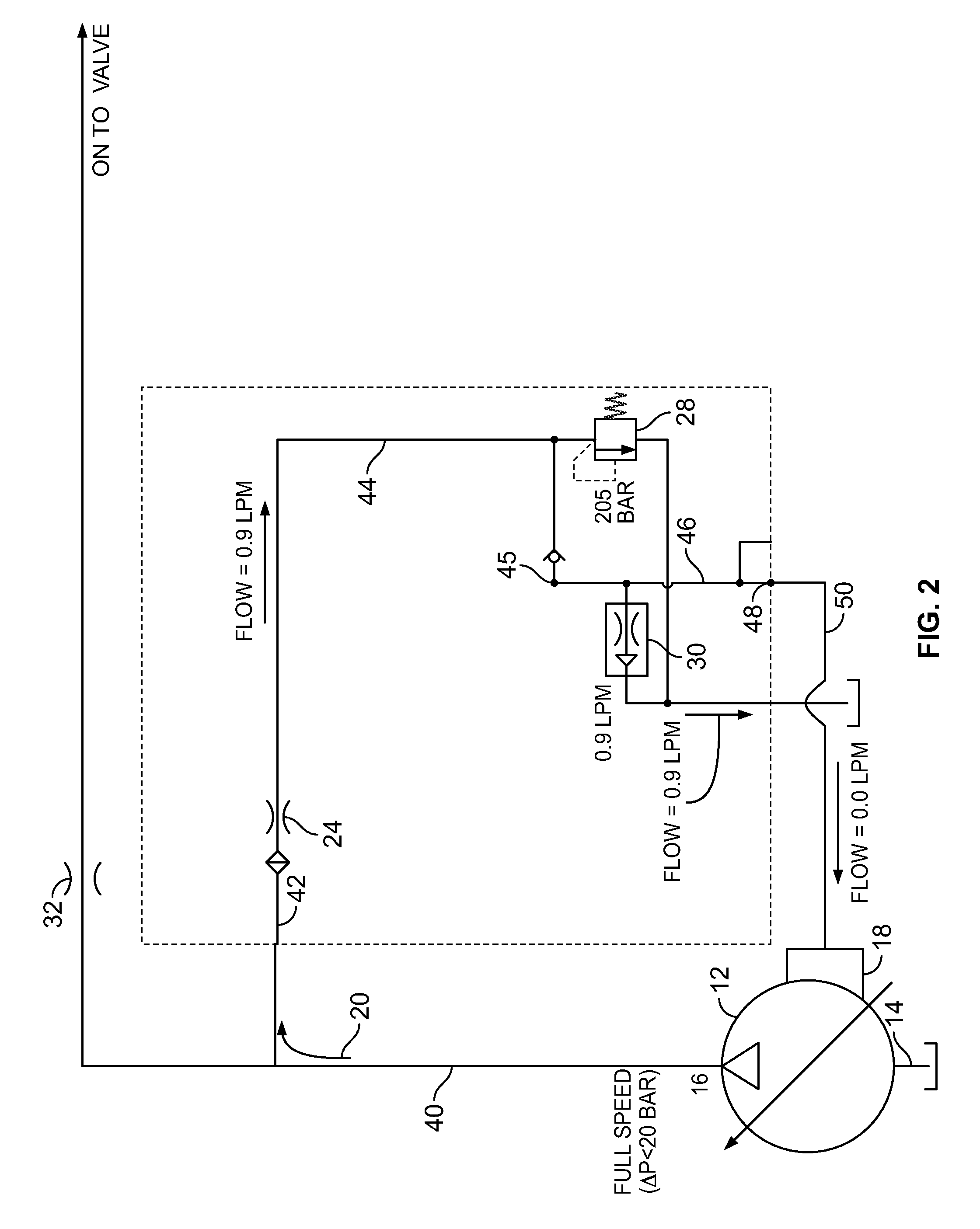
[0014]FIG. 1 shows a fragmentary schematic of a hydraulic system 10 for use in a hydraulically operated machine, such as a loader-backhoe (not shown). Hydraulic system 10 is an open center hydraulic system that employs a variable displacement pump 12. For purposes of understanding the present application, the values provided for operating parameters of variable displacement pump 12, as well as other components associated with the exemplary embodiment, may vary significantly from the provided values in other applications, and are not intended to be limiting.

[0015]Variable displacement pump 12 includes a sensing port 18 that is in selectable fluid communication with either of fluid circuits 20, 22. As shown in FIG. 1, a solenoid valve 26 may be used by an operator of the machine to select between fluid circuits 20, 22. Fluid circuits 20, 22 represent “signal” circuits that control operation of variable displacement pump 12. Variable displacement pump 12 operates within the “margin req...


PUM


Abstract

An open center hydraulic system that includes a variable displacement pump having an inlet, an outlet and a sensing port, the pump configured to provide reduced fluid flow in response to a predetermined fluid pressure differential between the outlet and the sensing port. A first fluid circuit and a second fluid circuit each serve as signal lines with the pump sensing port. During operation of the second fluid circuit, reduced fluid flow from the pump outlet is achieved as a result of the sum of induced fluid pressure reductions of respective controlled pressure reduction devices approaching the predetermined pump fluid pressure differential.

Description

FIELD OF THE INVENTION[0001]The present invention relates generally to hydraulic systems. It relates more particularly to open center hydraulic systems.SUMMARY OF THE INVENTION[0002]Many work vehicles have elongate members or linkages that are controlled by hydraulic actuators. When the hydraulic actuators are filled with fluid, typically under the control of hydraulic spool valves, the members move with respect to the work vehicle.[0003]One way to increase the craning and breakout specifications on the work vehicle, such as a loader-backhoe, would be to increase the operating pressure of the hydraulic system. However, increasing the operating pressure poses a number of problems. First, the vehicle structure may not be able to withstand dynamic loads that may be encountered during operation at an increased hydraulic pressure and full operating speed. Second, maintaining an increased operating pressure would require increased power requirements if the flow of hydraulic fluid remains ...

Claims


Application Information

Patent Timeline
IPC IPC(8): F15B11/16F15B21/08
CPCF04B49/002F15B11/028F15B21/082F15B2211/20553F15B2211/85F15B2211/41509F15B2211/6346F15B2211/76F15B2211/253
Inventor LECH, RICHARD J.ANDERSON, GARRETTHENNEMANN, MATTHEW J.ANDERSON, C. DAVID
Owner CNH IND AMERICA LLC
Learn More