Field olfactometer with differential flow-based dynamic dilution
- Summary
- Abstract
- Description
- Claims
- Application Information
AI Technical Summary
Benefits of technology
Problems solved by technology
Method used
Image
Examples
Embodiment Construction
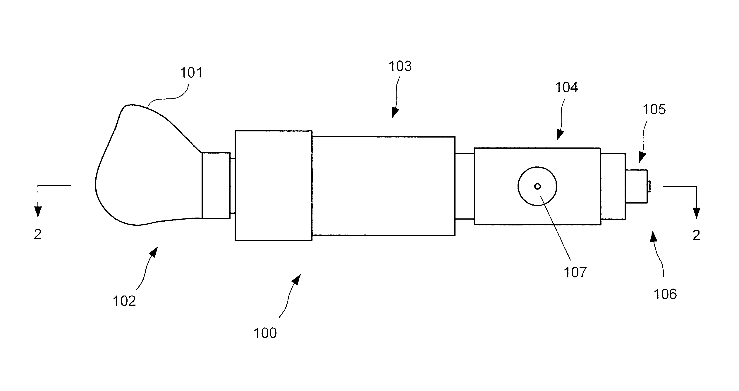
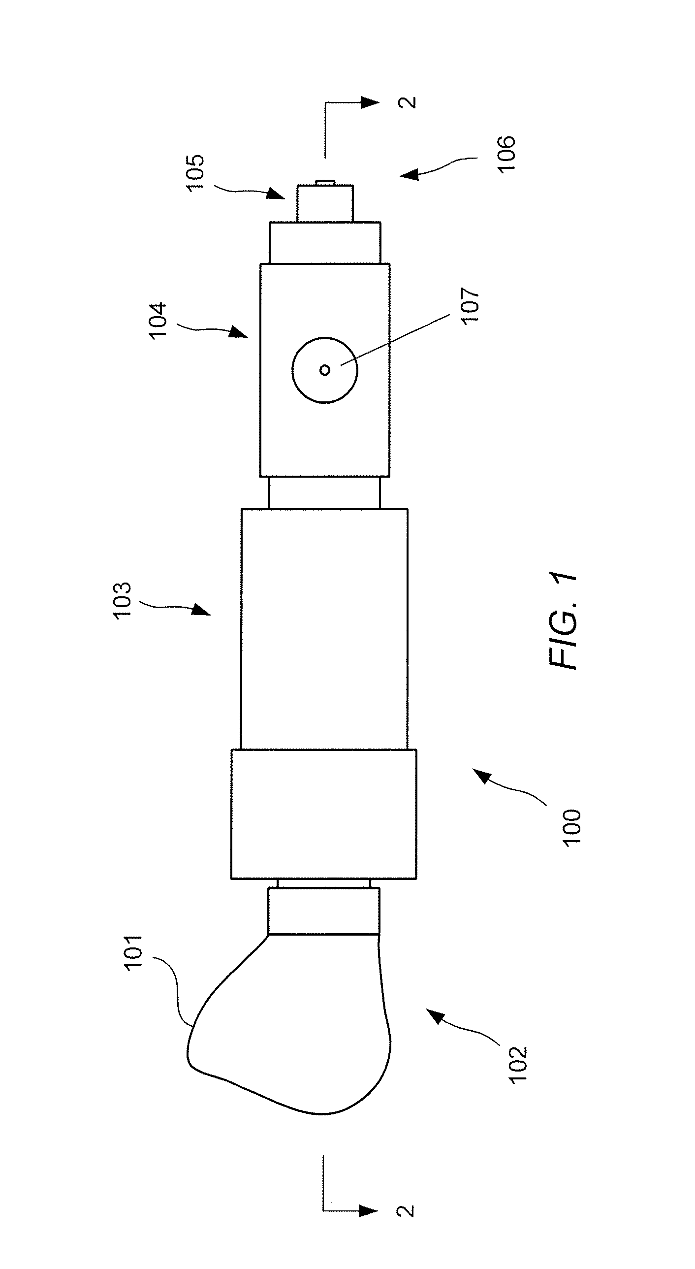
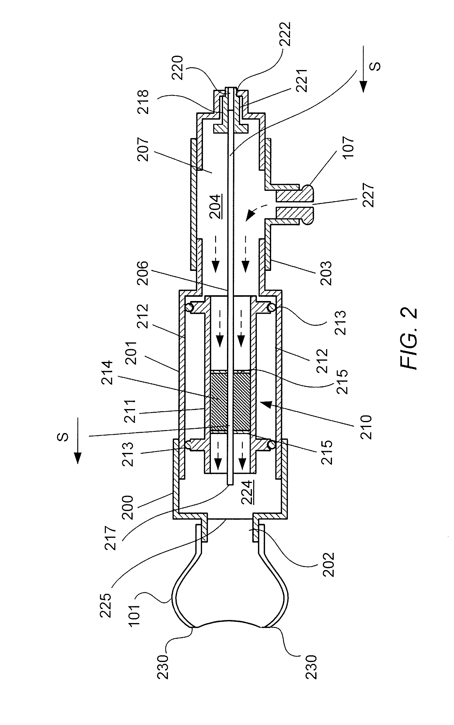
[0027]A field olfactometer 100 embodying the principles of the invention may be described with reference to FIGS. 1 through 3. As shown in FIG. 1, olfactometer 100 includes a mask 101 at an outlet end 102 of the olfactometer. Mask 101 is connected directly to one end of a filter housing 103. The end of filter housing 103 opposite the end connected to mask 101 is connected to a diluent inlet housing 104 which provides an inlet for diluent air into the olfactometer. The inlet for diluent air in this exemplary form of the invention is associated with a flow meter 107 mounted on diluent inlet housing 104. A sample inlet housing 105 is also connected to diluent inlet housing 104 at an inlet end 106 of the olfactometer opposite outlet end 102. As will be discussed below with reference to the section view shown in FIG. 2, the various housings of olfactometer 100 define a sample flow path and a diluent flow path through the device, both of which lead to a mixing chamber which is open to mas...
PUM
 Abstract
Description
Claims
Application Information
 - R&D
- Intellectual Property
- Life Sciences
- Materials
- Tech Scout
- Unparalleled Data Quality
- Higher Quality Content
- 60% Fewer Hallucinations
Browse by: Latest US Patents, China's latest patents, Technical Efficacy Thesaurus, Application Domain, Technology Topic, Popular Technical Reports.
© 2025 PatSnap. All rights reserved.Legal|Privacy policy|Modern Slavery Act Transparency Statement|Sitemap|About US| Contact US: help@patsnap.com


